A device called a toroid (figure) is often used to create an almost uniform magetic fiedl in some enclosed area. The device consists of a conducting wire wraped around a ring (a torus) made of a non conducting material. For a toroid having N closely spaced turns of wire, calculate the magnetic field in the region occupied by the torus, a distasnce r from the centre.
To calculate the magnetic field inside a toroid at a distance r from the center, we can follow these steps:
Step 1: Understand the Configuration
A toroid is a ring-shaped object made by wrapping a conducting wire around a non-conducting material. It has N closely spaced turns of wire and carries a current I.
Step 2: Apply Ampere's Law
According to Ampere's Law, the line integral of the magnetic field B around a closed loop is equal to the permeability of free space μ0 times the total current Ienc enclosed by the loop:
∮B⋅dl=μ0Ienc
Step 3: Define the Path of Integration
For a toroid, we consider a circular path of radius r (where r is the distance from the center of the toroid) for the line integral. The length of this path is:
dl=2πr
Step 4: Calculate the Enclosed Current
The total current enclosed by the loop at radius r is the product of the number of turns N and the current I:
Ienc=N⋅I
Step 5: Substitute into Ampere's Law
Substituting the values into Ampere's Law gives:
B⋅(2πr)=μ0(N⋅I)
Step 6: Solve for the Magnetic Field B
Rearranging the equation to solve for B:
B=μ0NI2πr
Conclusion
Thus, the magnetic field B inside the toroid at a distance r from the center is given by:
B=μ0NI2πr
A toroid is a ring-shaped object made by wrapping a conducting wire around a non-conducting material. It has N closely spaced turns of wire and carries a current I.
According to Ampere's Law, the line integral of the magnetic field B around a closed loop is equal to the permeability of free space μ0 times the total current Ienc enclosed by the loop:
For a toroid, we consider a circular path of radius r (where r is the distance from the center of the toroid) for the line integral. The length of this path is:
The total current enclosed by the loop at radius r is the product of the number of turns N and the current I:
Substituting the values into Ampere's Law gives:
Rearranging the equation to solve for B:
Thus, the magnetic field B inside the toroid at a distance r from the center is given by:
Topper's Solved these Questions
- MAGNETICSBOOK - DC PANDEY ENGLISHCHAPTER - MAGNETICSEXERCISE - INTRODUCTORY EXERCISE
1 Videos
- MAGNETICSBOOK - DC PANDEY ENGLISHCHAPTER - MAGNETICSEXERCISE - SUBJECTIVE_TYPE
1 Videos
- MAGNETIC FIELD AND FORCESBOOK - DC PANDEY ENGLISHCHAPTER - MAGNETIC FIELD AND FORCESEXERCISE - Medical entrance s gallery
59 Videos
- MAGNETISM AND MATTERBOOK - DC PANDEY ENGLISHCHAPTER - MAGNETISM AND MATTEREXERCISE - Medical gallery
1 Videos
Similar Questions
PQRS is a square region of side 2a in the plane of paper. A uniform magnetic field B, directed perpendicular to the plane of paper and into its plane is confined within this square region. A square loop of side 'a' and made of a conducting wire of resistance R is moved at a constant velocity →v from left to right in the plane of paper as shown. Obviously, the square loop will enter the magnetic field at some time and then leave it after some time. During the motion of loop, whenever magnetic flux through it changes, emf will be induced resulting in induced current. Let the motion of the square loop be along x-axis and let us measure x coordinate of the centre of square loop from the centre of the square magnetic field region (taken as origin). Thus, x coordinate will be positive if the centre of square loop is to the right of the origin O (centre of magnetic field) and negative if centre is to the left.
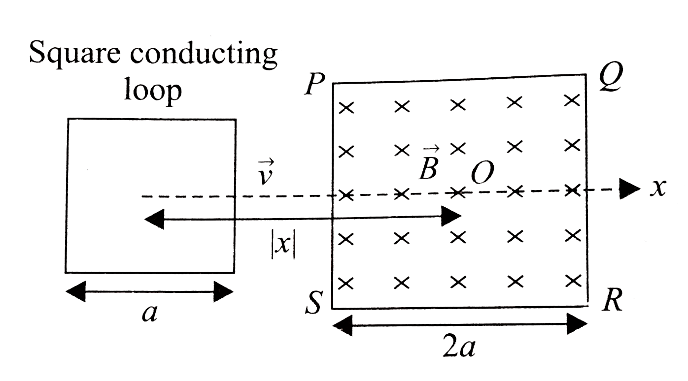
External force required to maintain constant velocity of the loop for x=−95a will be
View SolutionPQRS is a square region of side 2a in the plane of paper. A uniform magnetic field B, directed perpendicular to the plane of paper and into its plane is confined within this square region. A square loop of side 'a' and made of a conducting wire of resistance R is moved at a constant velocity →v from left to right in the plane of paper as shown. Obviously, the square loop will enter the magnetic field at some time and then leave it after some time. During the motion of loop, whenever magnetic flux through it changes, emf will be induced resulting in induced current. Let the motion of the square loop be along x-axis and let us measure x coordinate of the centre of square loop from the centre of the square magnetic field region (taken as origin). Thus, x coordinate will be positive if the centre of square loop is to the right of the origin O (centre of magnetic field) and negative if centre is to the left.
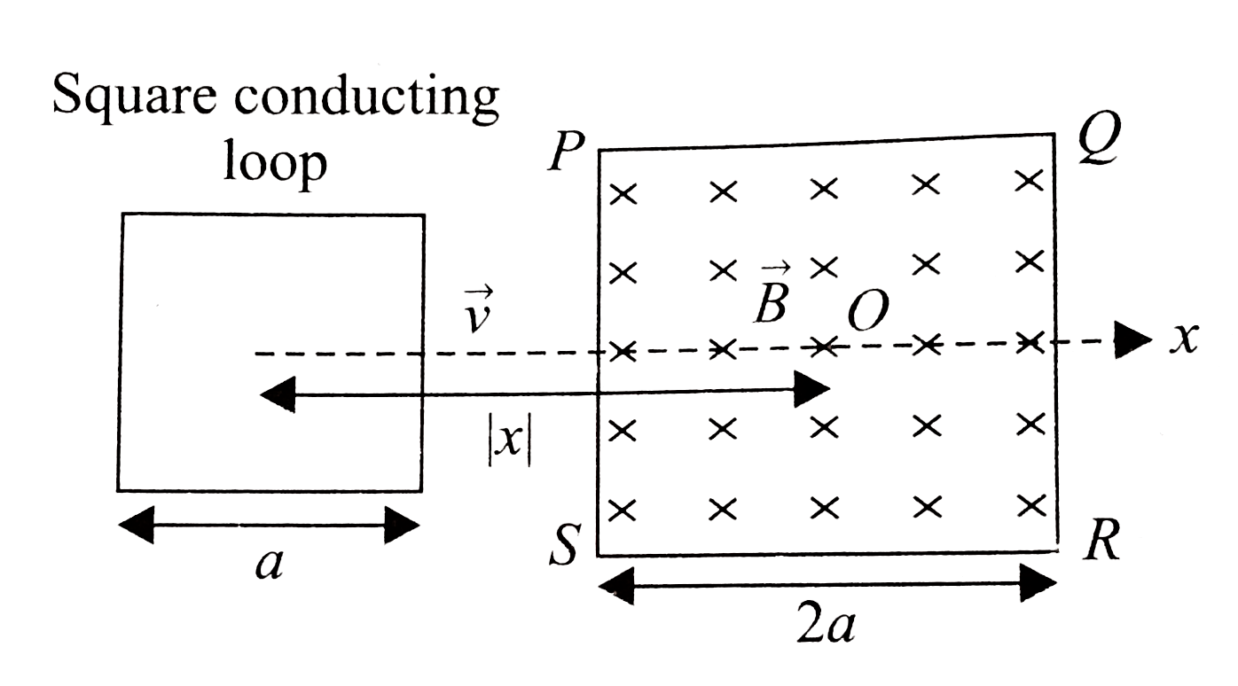
For x=a/4
(i) magnetic flux through the loop,
(ii) induced current in the loop and
(iii) external force required to maintain constant velocity of the loop, will be
View SolutionPQRS is a square region of side 2a in the plane of paper. A uniform magnetic field B, directed perpendicular to the plane of paper and into its plane is confined within this square region. A square loop of side 'a' and made of a conducting wire of resistance R is moved at a constant velocity →v from left to right in the plane of paper as shown. Obviously, the square loop will enter the magnetic field at some time and then leave it after some time. During the motion of loop, whenever magnetic flux through it changes, emf will be induced resulting in induced current. Let the motion of the square loop be along x-axis and let us measure x coordinate of the centre of square loop from the centre of the square magnetic field region (taken as origin). Thus, x coordinate will be positive if the centre of square loop is to the right of the origin O (centre of magnetic field) and negative if centre is to the left.
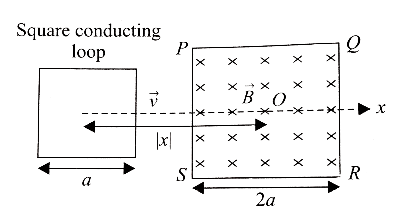
For x=−9a/5, magnitude of induced current and its direction as seen from above will be:
View SolutionA rectangular conducting loop consists of two wires on two opposite sides of length l joined together by rods of length d. The wires are each of the same material but with cross-sections differing by a factor of 2. The thicker wire has a resistance R and the rods are of low resistance, which in turn are connected to a constant voltage source V0. The loop is placed in a uniform magnetic field B at 45∘ to its plane. Find τ, the torque exerted by the magnetic field on the loop about an axis through the centres of rods.
View SolutionA ring made of insulating material is rolling without slipping on a horizontal surface with velocity of centre of mass V0. A conducting wire of length 2R (R = radius of ring) is fixed between two points of the circumference. At an instant, the wire is in vertical position as shown in figure. A uniform magnetic field B exists perpendicular to the plane of the ring. The magnitude to emf induced between the ends of wire is
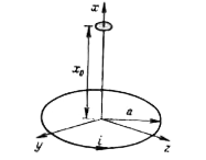
View SolutionA horizontal flat coil of radius a made of w turns of wire carrying a current sets up a magnetic field. A horizontal conducting ring of radius r is placed at a distance x0 from the centre of the coil (Fig. 30.6). The ring is dropped. What e.m.f. will be established in it? Express the e.m.f. in terms of the speed.
View SolutionA person wants to roll a solid non-conducting spherical ball of mass m and radius r on a surface whose coefficient of static friction is μ. He placed the ball on the surface wrapped with n turns of closely packed conducting coils of negligible mass at the diameter.
By some arrangement he is able to pass a current i through the coils in anti-clockwise direction when viewed downwards from point P. A constant horizontal magnetic field →B is present throughout the space along the positive x direction as shown in the figure. (Assume μ is large enough to help pure rolling motion and initially the plane of the coils is perpendicular to the y-axs)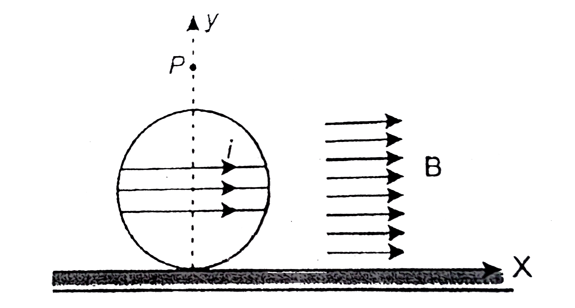
If current i is passed through the coil then
View SolutionA person wants to roll a solid non-conducting spherical ball of mass m and radius r on a surface whose coefficient of static friction is μ. He placed the ball on the surface wrapped with n turns of closely packed conducting coils of negligible mass at the diameter.
By some arrangement he is able to pass a current i through the coils in anti-clockwise direction when viewed downwards from point P. A constant horizontal magnetic field →B is present throughout the space along the positive x direction as shown in the figure. (Assume μ is large enough to help pure rolling motion and initially the plane of the coils is perpendicular to the y-axs)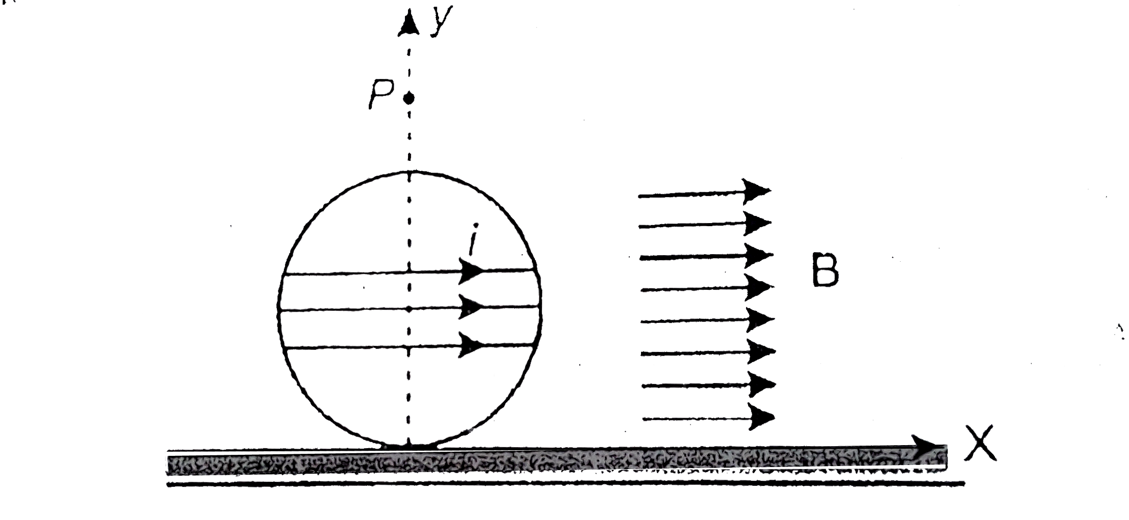
The angular velocity of the ball when it is has rotated through an angle θ is (θ<180∘)
View Solution
