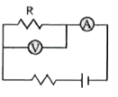
Which of the following wiring diagrams could be used to experimentally determine R using ohm's law? Assume an ideal voltmeter and an ideal ammeter. Solution in Telugu


The correct Answer is:B
Step by step video, text & image solution for Which of the following wiring diagrams could be used to experimentally determine R using ohm's law? Assume an ideal voltmeter and an ideal ammeter. by Physics experts to help you in doubts & scoring excellent marks in Class 12 exams.
Updated on:21/07/2023Topper's Solved these Questions
- CURRENT ELECTRICITYBOOK - AAKASH SERIESCHAPTER - CURRENT ELECTRICITYEXERCISE - EXERCISE - IB
44 Videos
- CURRENT ELECTRICITYBOOK - AAKASH SERIESCHAPTER - CURRENT ELECTRICITYEXERCISE - EXERCISE - II
84 Videos
- CURRENT ELECTRICITYBOOK - AAKASH SERIESCHAPTER - CURRENT ELECTRICITYEXERCISE - PROBLEMS
94 Videos
- CURRENT ELECTRICITYBOOK - AAKASH SERIESCHAPTER - CURRENT ELECTRICITYEXERCISE - PROBLEMS (LEVEL-II)
26 Videos
- DUAL NATURE OF RADIATION AND MATTERBOOK - AAKASH SERIESCHAPTER - DUAL NATURE OF RADIATION AND MATTEREXERCISE - PRACTICE EXERCISEX
44 Videos
Similar Questions
(A): Most of good conductors of heat are also good conductors of electricity and vice versa.
(R): Mainly electrons are responsible for these conductions.
View SolutionThe number of electrons striking the screen of CRT is 7.5×10¹⁵ in 10 s. Calculate the electric current.
View SolutionA total of 6.0×10¹⁶ electrons pass through any cross - section of a conducting wire per second. Find the current.
View SolutionA battery of emf 10 V and internal resistance 3Ω is connected to a resistor. If the current in the circuit is 0.5 A, what is the resistance of the resistor? What is the terminal voltage of the battery when the circuit is closed?
View SolutionTwo separate monochromatic light beams A and B of the same intensity are falling normally on a unit area of a metallic surface. Their wave lengths are λA and λB, respectively. Assuming that all the incident light is used in ejecting the photoelectrons the ratio of the photoelectrons from the beam A to that from B is :
View Solution
Assertion : In the circuit shown in figure ammeter and voltmeter are non-ideal. Why positions of ammeter and voltmeter are changed, reading of ammeter will increase while of voltmeter will decrease.
Reason : Resistance of an ideal ammeter is zero while that of an ideal voltmeter is infinite.
View SolutionWhat is the resistance of ideal ammeter and ideal voltmeter?
View SolutionWhich of the following wiring diagrams could be used to experimentally determine R using ohm's law? Assume an ideal voltmeter and an ideal ammeter.
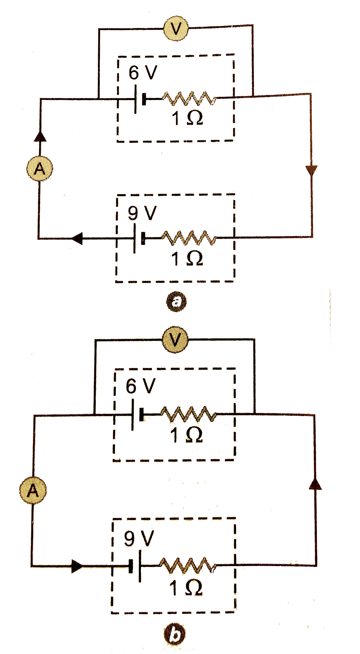
View SolutionIn the two electron circuit determine the readings of ideal ammeter (A) ideal voltmeter (V)

View SolutionIf the positions of voltmeter and ammeter are interchanged in Ohm's law circuit, then
View SolutionIn the diagram shown, the reading of voltmeter is 20 V and that of ammeter is 4 A . The value of R should be (Consider given ammeter and voltmeter are not ideal)
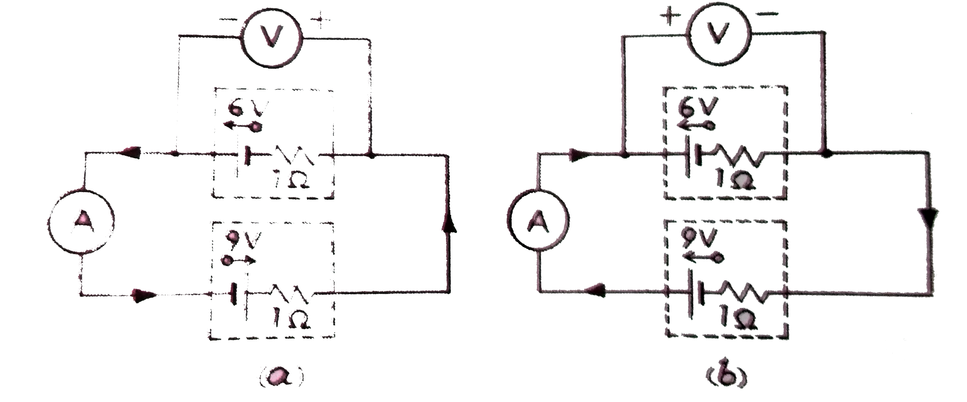
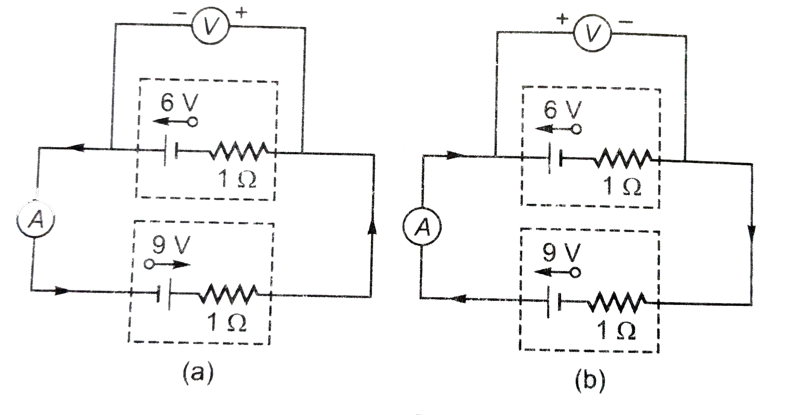
View Solutionनिम्न परिपथों (a) तथा (b) में आदर्श अमीटर A तथा आदर्श वोल्टमीटर V के पाठ्यांक ज्ञात कीजिए ।

View Solutionपरिपथ चित्र (a) व (b) में आदर्श अमीटर A तथा आदर्श वोल्ट्मीटर V के पाठ लिखिए|

View Solutionओम के नियम को लिखें , ऐमीटर तथा वोल्टमीटर द्वारा इस नियम की जाँच करें ।
View Solutionआदर्श वोल्टमीटर व आदर्श अमीटर के प्रतिरोध लिखिए।
View Solution