In a diode AM detector with the output circuit consists of R=1MΩ and C=1pF would be more suitable for detecting a carrier signal of
1MHz
0.1 MHz
0.5MHz
10MHz
The correct Answer is:D
Here, RC=106×10−12=10−6s
for demodulation, 1vc<<RC
vc=1RC or vc>>1106=106Hz.
∴vc>>106Hz
Topper's Solved these Questions
- COMMUNITCATION SYSTEMSBOOK - NCERT FINGERTPS ENGLISHCHAPTER - COMMUNITCATION SYSTEMSEXERCISE - HOTS
20 Videos
- COMMUNITCATION SYSTEMSBOOK - NCERT FINGERTPS ENGLISHCHAPTER - COMMUNITCATION SYSTEMSEXERCISE - NCERT
9 Videos
- ATOMS BOOK - NCERT FINGERTPS ENGLISHCHAPTER - ATOMS EXERCISE - Assertion And Reason
15 Videos
- CURRENT ELECTRICITYBOOK - NCERT FINGERTPS ENGLISHCHAPTER - CURRENT ELECTRICITYEXERCISE - Assertion And Reason
15 Videos
Similar Questions
Knowledge Check
A series LCR circuit has R=5Ω,L=40mH and C=1μF, the bandwidth of the circuit is
A10 HzB20 HzC30 HzD40 HzThe carrier freqeuncy of a station is 40 MHz. A resistor of 10k Ω and capacitor of 12 pF are available in the detector circuit. The possible value of C will be
A12B8.2C5.6DAll of theseThe carrier freqeuncy of a station is 40 MHz. A resistor of 10k Ω and capacitor of CpF are available in the detector circuit. The possible value of C will be
A12B8.2C5.6DAll of these
An LCR circuit contains R=50Ω,L=1mH and C=0.1μF. The impedence of the circuit will be minimum for a frequency of
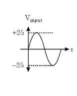
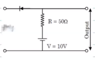
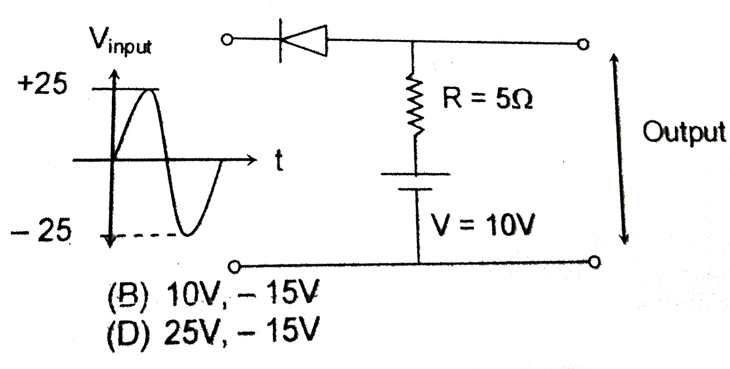
View SolutionAn ideal diode is connected in a circuit with resistance R=50ΩandV=10V. If an AC input signal shown in the figure is given to the circuit, then the maximum and minimum value of output voltage (without load) is


View Solution
An ideal diode is connected in a circuit with resistance R=5Ω and V=10 volt as shown in figure maximum and minimum value of output voltage. When no load applied is (assume diode to be ideal)
View SolutionAn experiment is preformed to determine the I−V characteristics of a Zener diode, which has a protective resistance of R=100Ω, and maximum power of dissipation rating of 1 W. The minimum voltage range of the DC source in the circuit is :-
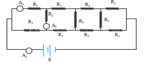
View SolutionIn the given circuit, R1 = 10Ω R2=6Ω and E = 10V, then correct statement is

View Solution
