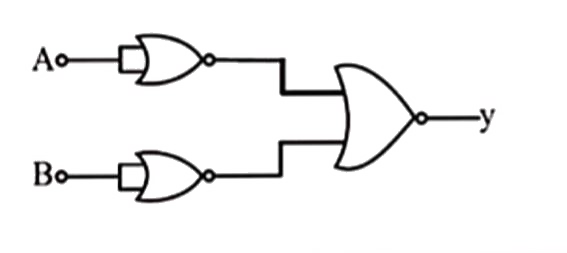
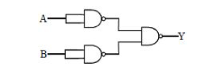
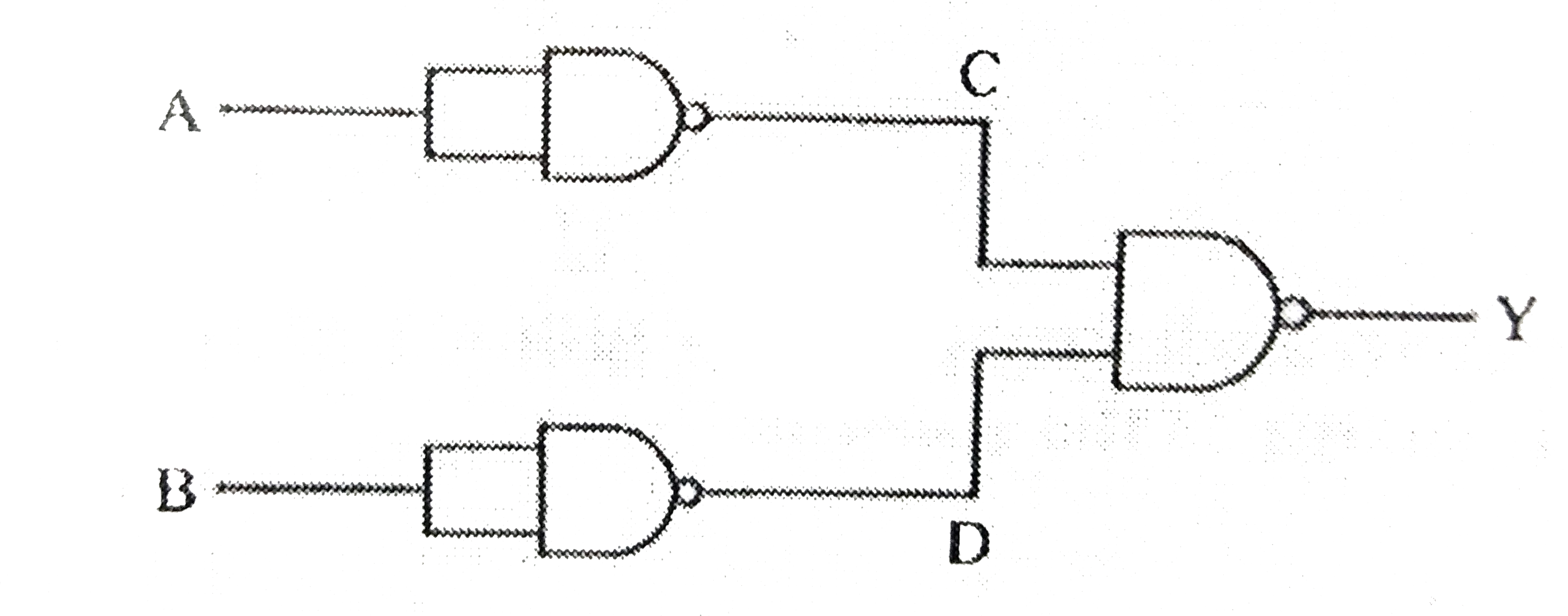
Draw the output waveform X, using the given inputs A and B for the logic circuit shows below. Also, identify the logic operation performed by this circuit.

Both are NAND Gates.

Topper's Solved these Questions
- XII BOARDSBook:XII BOARDS PREVIOUS YEARChapter:XII BOARDSExercise:SET-III, DELHI BOARD
Explore 8 Videos
- XII BOARDSBook:XII BOARDS PREVIOUS YEARChapter:XII BOARDSExercise:[Set- II]
Explore 8 Videos
- XII BOARDSBook:XII BOARDS PREVIOUS YEARChapter:XII BOARDSExercise:PHYSICS (Theory) [SET -I]
Explore 33 Videos
- SAMPLE PAPER 2019Book:XII BOARDS PREVIOUS YEARChapter:SAMPLE PAPER 2019Exercise:SECTION D
Explore 6 Videos
Similar Questions
Draw the output waveformed at X, using the given inputs A and B for the logic circuit shows below. Also, identify the logic operation performed by this circuit.

View SolutionDrawn the output waveform at X, using thye given inputs A and B for the logic circuit shown in Fig. Also identify the logic operation performed by this circuit.

View Solution
Knowledge Check
Identify the operation performed by the circuit given below-
 ANOTBANDCORDNAND
Identify the operation performed by the circuit given below :-
 ANOTBANDCORDOR
Identify the operation performed by the circuit given below:
 ANOTBANDCORDNAND
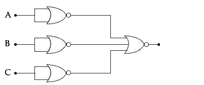
Identify the logic operation performed by the circuit given here.

View SolutionWrite the truth table for the logic circuit shown below and identify the logic operation performed by circuit.

View SolutionIdentify the operation performed by the circuit given below:

View SolutionIdentify the operation performed by the circuit given below :-

View SolutionIdentify the logic operation carried out by the following circuit

View Solution