A 4μF capacitor is connected to a battery of emf 24V. Through a resistance of 5MΩ and a switch which is kept open initially. Internal resistance of the battery is negligible. Switch is closed at t=0. Potential difference across capacitor and resistor at t=0 are respectively.
12V, 12V
0V, 24V
24V, 0V
6V, 18V
The correct Answer is:B
To solve the problem, we need to determine the potential difference across the capacitor and the resistor at the moment the switch is closed (t=0).
1. Understanding the Circuit Configuration:
- We have a capacitor (C = 4 µF) connected to a battery (emf = 24 V) through a resistor (R = 5 MΩ). The switch is initially open.
2. Closing the Switch at t=0:
- When the switch is closed at t=0, the circuit is completed, and current starts to flow.
3. Initial Condition of the Capacitor:
- At t=0, the capacitor is uncharged. Therefore, the initial voltage across the capacitor (V_C) is 0 V. This is because a capacitor initially behaves like a short circuit when it has no charge.
4. Applying Kirchhoff’s Voltage Law:
- According to Kirchhoff’s Voltage Law, the sum of the potential differences in a closed loop must equal the emf supplied by the battery.
- The total voltage provided by the battery is 24 V. Since the capacitor has 0 V across it at t=0, all the voltage from the battery appears across the resistor.
5. Calculating the Voltage Across the Resistor:
- Since the voltage across the capacitor is 0 V, the voltage across the resistor (V_R) must be equal to the emf of the battery:
VR=Vbattery−VC=24V−0V=24V
6. Final Answer:
- Therefore, at t=0, the potential difference across the capacitor is 0 V and across the resistor is 24 V.
Summary of Results:
- Voltage across the capacitor (V_C) = 0 V
- Voltage across the resistor (V_R) = 24 V
- We have a capacitor (C = 4 µF) connected to a battery (emf = 24 V) through a resistor (R = 5 MΩ). The switch is initially open.
- When the switch is closed at t=0, the circuit is completed, and current starts to flow.
- At t=0, the capacitor is uncharged. Therefore, the initial voltage across the capacitor (V_C) is 0 V. This is because a capacitor initially behaves like a short circuit when it has no charge.
- According to Kirchhoff’s Voltage Law, the sum of the potential differences in a closed loop must equal the emf supplied by the battery.
- The total voltage provided by the battery is 24 V. Since the capacitor has 0 V across it at t=0, all the voltage from the battery appears across the resistor.
- Since the voltage across the capacitor is 0 V, the voltage across the resistor (V_R) must be equal to the emf of the battery:
VR=Vbattery−VC=24V−0V=24V
- Therefore, at t=0, the potential difference across the capacitor is 0 V and across the resistor is 24 V.
- Voltage across the capacitor (V_C) = 0 V
- Voltage across the resistor (V_R) = 24 V
Topper's Solved these Questions
- CURRENT ELECTRICITYBOOK - MODERN PUBLICATIONCHAPTER - CURRENT ELECTRICITYEXERCISE - Objective Type Questions (MULTIPLE CHOICE QUESTIONS) (B. MULTIPLE CHOICE QUESTION FOR COMPETITIVE EXAMINATIONS)
20 Videos
- CURRENT ELECTRICITYBOOK - MODERN PUBLICATIONCHAPTER - CURRENT ELECTRICITYEXERCISE - Objective Type Questions (MULTIPLE CHOICE QUESTIONS) (B. MULTIPLE CHOICE QUESTION JEE (MAIN) & OTHER STATE BOARDS FOR ENGINEERING ENTRANCE)
45 Videos
- CURRENT ELECTRICITYBOOK - MODERN PUBLICATIONCHAPTER - CURRENT ELECTRICITYEXERCISE - REVISION EXERCISES (NUMERICAL PROBLEMS)
24 Videos
- ATOMS BOOK - MODERN PUBLICATIONCHAPTER - ATOMS EXERCISE - Chapter Practice Test
16 Videos
- DUAL NATURE OF RADIATION AND MATTER BOOK - MODERN PUBLICATIONCHAPTER - DUAL NATURE OF RADIATION AND MATTER EXERCISE - CHAPTER PRACTICE TEST
15 Videos
Similar Questions
A 20(μ)Fcapacitor is joined to a battery of emf 6.0V through a resistance of 100(Ω).find the charge on the capacitor 2.0ms after the connections are made .
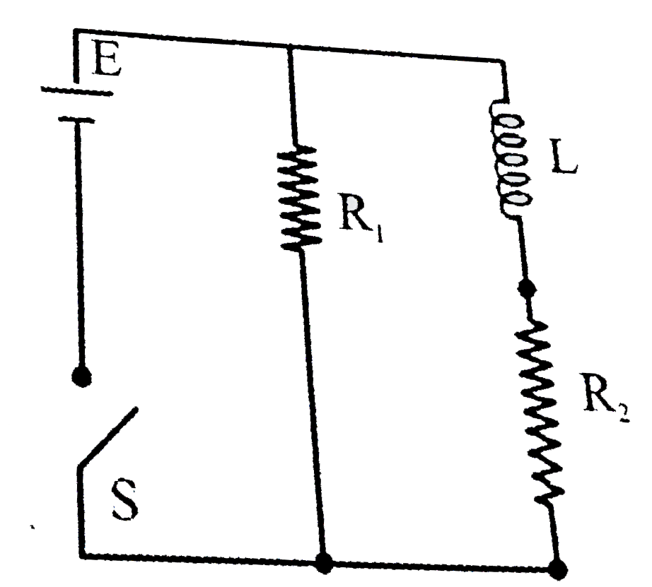
View SolutionAn inductor of inductance L = 400 mH and resistors of resistance R1=2Ω and R2=2Ω are connected to a battery of emf 12 V as shown in the figure. The internal resistance of the battery is negligible. The switch S is closed at t=0. The potential drop across L as a function of time is
View Solution
Knowledge Check
An inductor of inductance L = 400 mH and resistors of resistance R1=2Ω and R2=2Ω are connected to a battery of emf 12V as shown in the figure.The internal resistance of the battery is negligible.The switch S is closed at t = 0.The potential drop across L as a function of time is
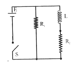 A12te−3tVB6(1−e−t0.2)VC12e−5tVD6e−5tV
An inductor of inductance L = 400 mH and resistors of resistance R1=2Ω and R2=2Ω are connected to a battery of emf 12 V as shown in the figure. The internal resistance of the battery is negligible. The switch S is closed at t=0. The potential drop across L as a function of time is
 A12te−3tVB6(1−e−t/0.2)VC12e−5tVD6e−5tV
In the circuit shown, the capacitor is initially uncharged. The switch S is closed at t = 0. Time after which voltage across capacitor and resistor are equal is:
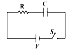 ARCln12BRCln2CRCln32DRC
An inductor of inductance L=400 mH and resistor of resistance R1=2(Ω)andR2=2(Ω) are connected to a battery of emf E = 12 Vas shown in the figure. The internal resistance of the battery is negligible. The switch S is closed at time t =0. What is the potential drop across L as a function of time? After the steady state is reached, the switch is opened. What is the direction and the magnitude of current through R1 as a function of time?
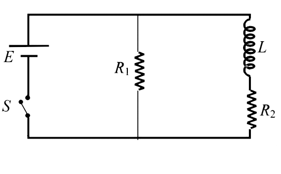
View SolutionAn inductor of inductance L=400mH and resistors of resistances R1=2Ω and R2=2Ω are connected to a battery of emf E=12V as shown in the figure. The internal resistance of the battery is negligible. The switch S is closed at time t=0.
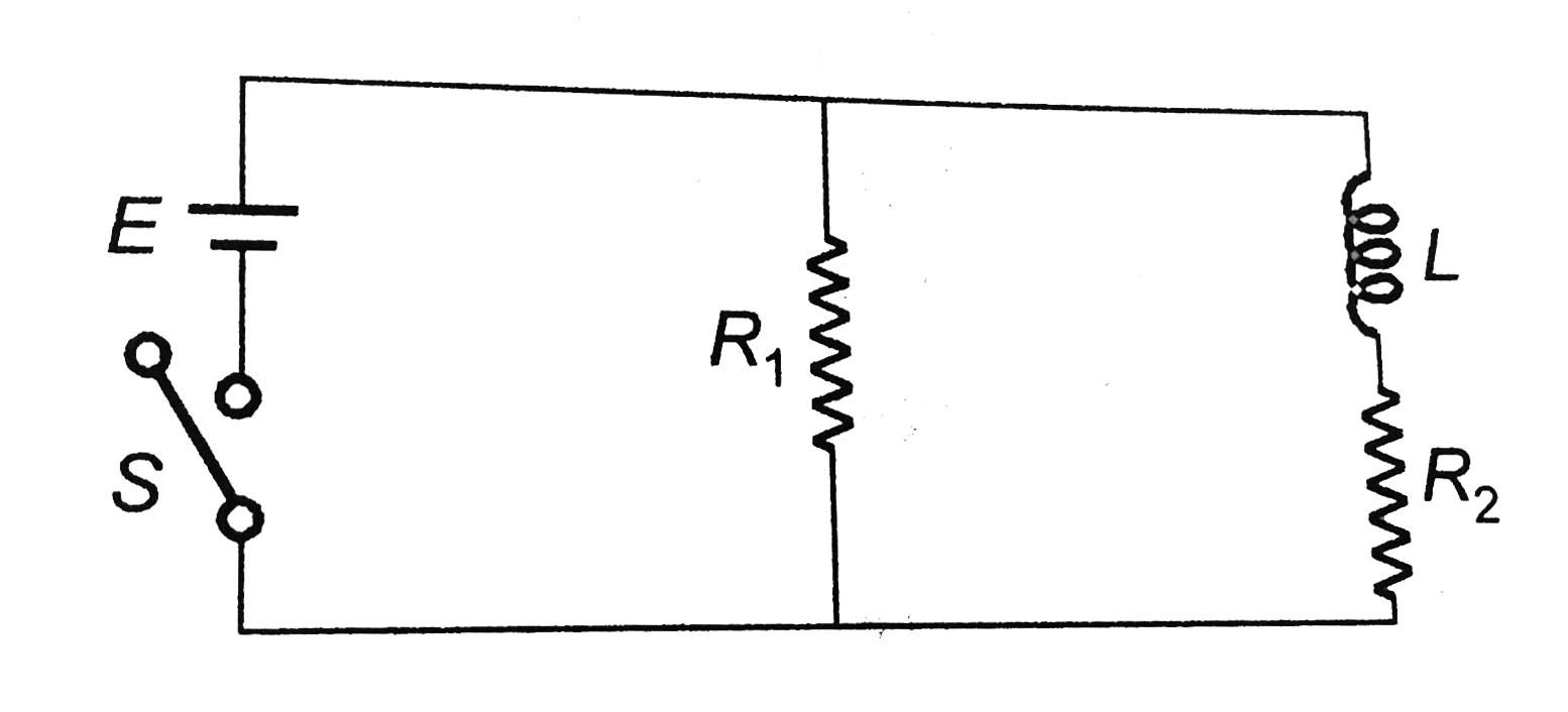
What is the potential dro across L s a function of time? After the steady state is reached, the switch is opened. What is the direction ad the magnitude of current throough R1 as a function of time?
View SolutionAn uncharged capacitor is connected to a 15 V battery through a resistance of 10Ω. It is found that in a time fo 2μs, potential difference across the capacitor. Take in (1.5) = 0.4.
View SolutionAn inductor of inductance L = 400 mH and resistors of resistance R1=2Ω and R2=2Ω are connected to a battery of emf 12 V as shown in the figure. The internal resistance of the battery is negligible. The switch S is closed at t=0. The potential drop across L as a function of time is

View SolutionAn uncharged capacitor of capacitance 8.0μF is connected to a battery of emf 6.0 V through a resistance of 24Ω, then
(i) The current in the circuit just after the connections are made is :
View Solution
