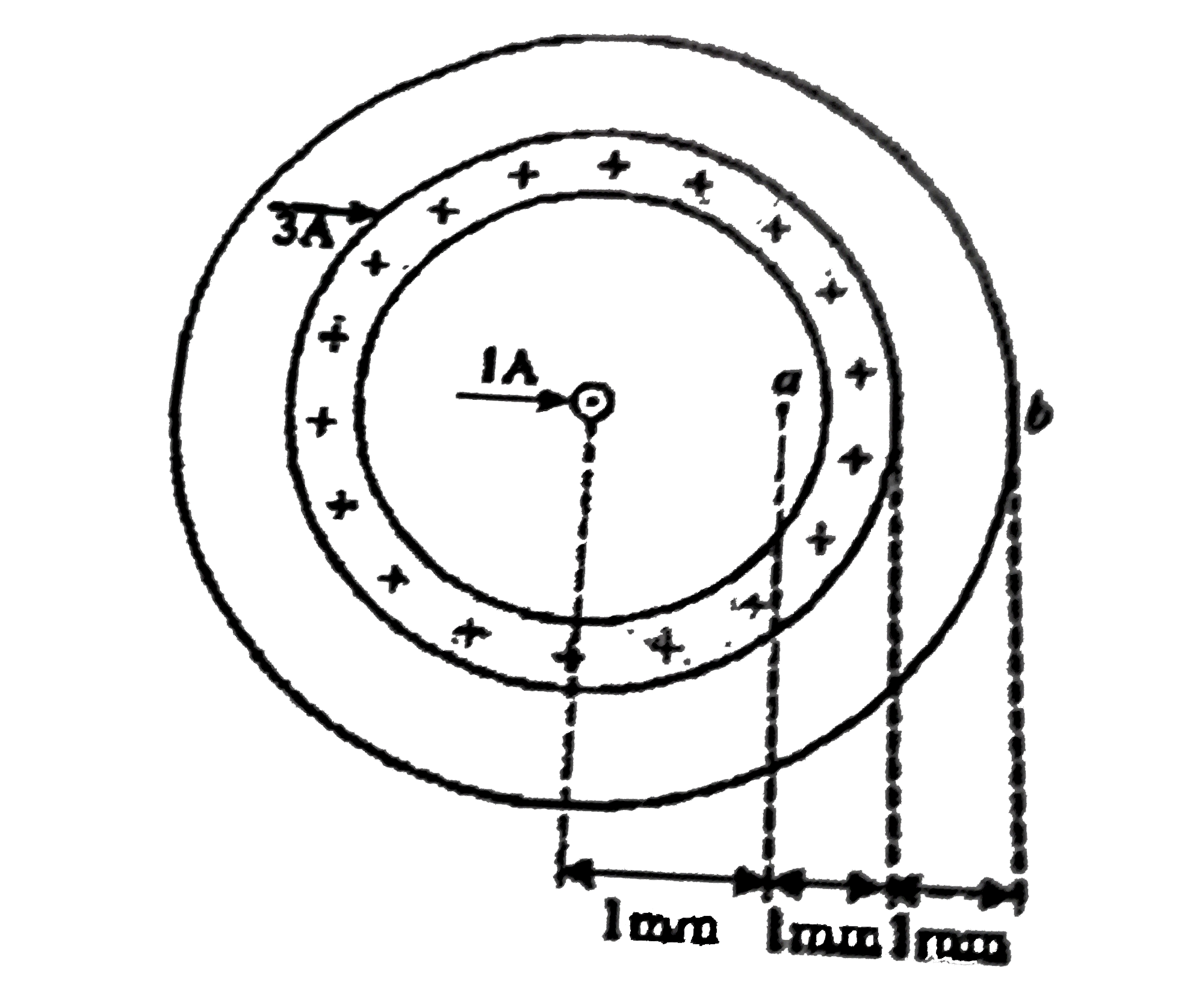
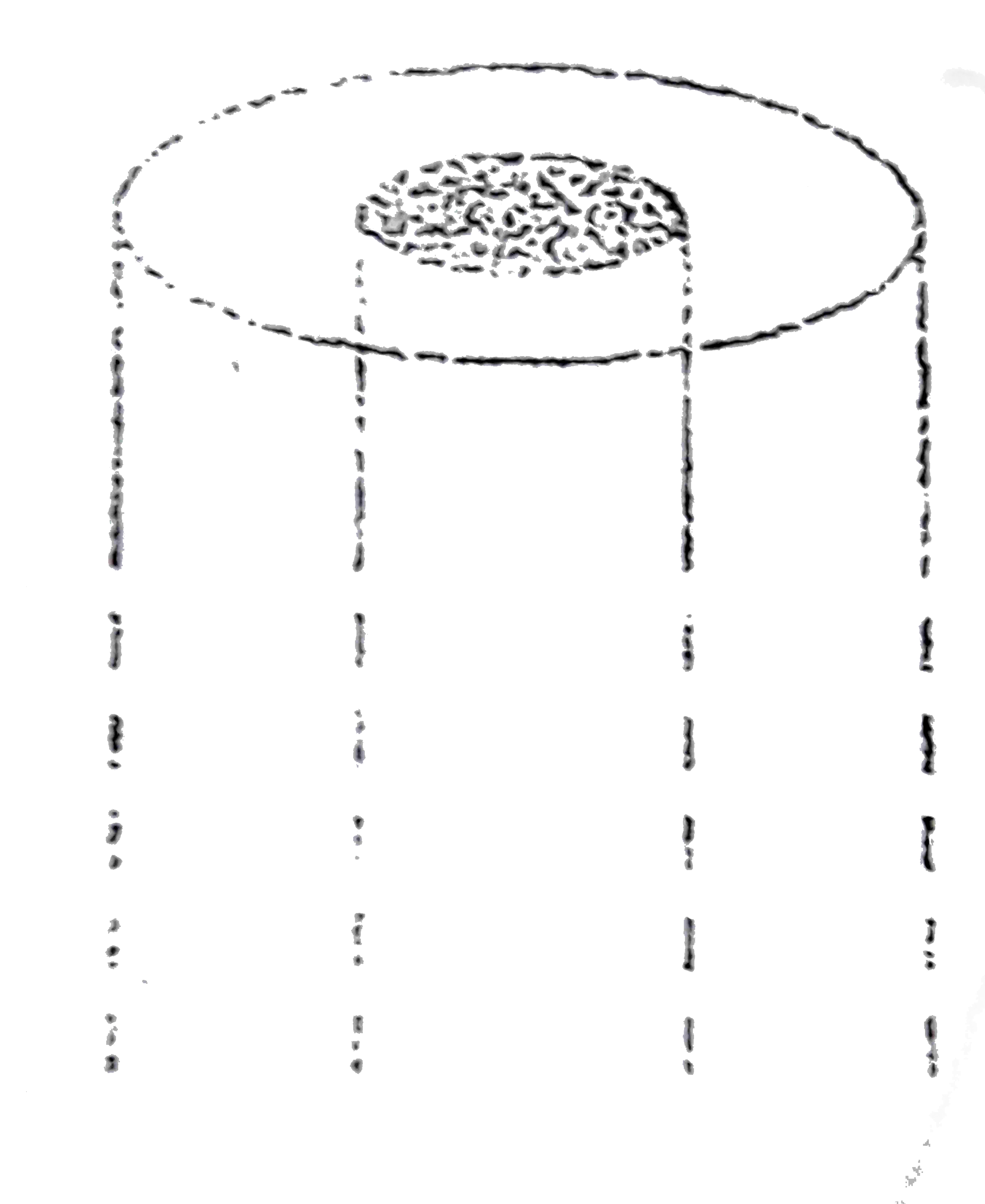
Figure given in the question is a cross-sectional view of a coaxial cable. The centre conductor is surrounded by a rubber layer, which is surrounded by an outer conductor, which is surrounded by another rubber layer. The current in the inner conductor is 1.0A out of the page, and the current in the outer conductor is 3.0A into the page. Determine the magnitude and direction of the magnetic field at points a and b.
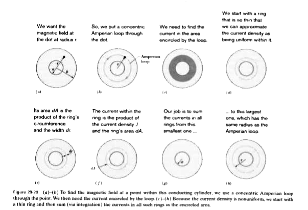
The point at which we want to evaluate →B is inside the material of the conducting cylinder, between its inner and outer radii. We note that the current distribution has cylindrical symmetry (it is the same all around the cross section for any given radius). Thus, the symmetry allows us to use Ampere.s law of find →B at the point. We first draw the Amperian loop shown in Fig. 29-29b. The loop is concentric with the cylinder and has radius r=3.0cm because we want to evaluate →B at that distance from the cylinder.s central axis.
Next, we must compute the current ienc that is encircled by the Amperian loop. However, we cannot set up a proportionality as in Eq. 29-38, because here the current is not uniformly distributed . Instead, we must integrate the current density magnitude from the cylinder.s inner radius a to the loop radius r, using the steps shown in Figs. 29-29c through h.
Calculations : We write the integral as
ienc=∫JdA=∫racr2(2πrdr)
=2πc∫rar3dr=2πc[r44]ra
=(πcr4−a42).
Note that in these steps we took the differential area dA to be the area of the thin ring in Figs. 29-29d-f and then replaced it with its equivalent, the product of the ring .s circumference 2πr and its thickness dr.
For the Amperian loop, the direction of integration indicated in Fig. 29-29b is (arbitarily) clockwise. Applying the right-hand rule for Ampere.s law to that loop, we find that we should take ienc as negative because the current is directed out of the page but our thumb is directed into the page.
We next evaluate the left side of Ampere.s law as we did in Fig. 29-28, and we again obtain Eq. 29-37. Then Ampere.s law
∮→B⋅dcecs=μ0ienc
gives us
B(2πr)=−μ0πc2(r4−a4)
Solving for B and substituting known data yield
B=−μ0c4r(r4−a4)
=−(4π×10−7T⋅m/A)(3.0×106A/m4)4(0.030m)×](0.030m)4−(0.020m)4]
=−2.0×10⁻⁵T
Thus, the magnetic field →B at a point 3.0cm from the central axis has magnitude
B=2.0×10⁵T
and forms magnetic field lines that are directed opposite our direction of integration , hence counterclockwise in Fig. 29-29b
Topper's Solved these Questions
- MAGNETIC FIELDS DUE TO CURRENTSBook:RESNICK AND HALLIDAYChapter:MAGNETIC FIELDS DUE TO CURRENTSExercise:Check point
Explore 4 Videos
- MAGNETIC FIELDS DUE TO CURRENTSBook:RESNICK AND HALLIDAYChapter:MAGNETIC FIELDS DUE TO CURRENTSExercise:Problems
Explore 45 Videos
- INTERFERENCE AND DIFFRACTION Book:RESNICK AND HALLIDAYChapter:INTERFERENCE AND DIFFRACTION Exercise:PRACTICE QUESTIONS (Integer Type)
Explore 6 Videos
- MAGNETIC FORCEBook:RESNICK AND HALLIDAYChapter:MAGNETIC FORCEExercise:Practice Questions (Integer type )
Explore 7 Videos
Similar Questions
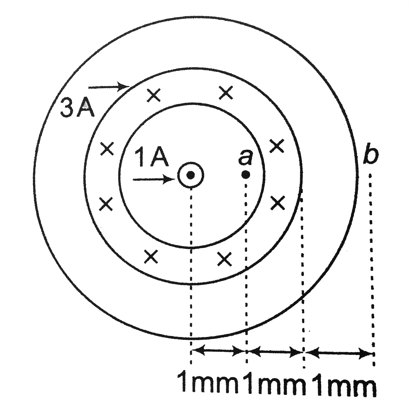
Figure given in the question is a cross-sectional view of a coaxial cable. The centre conductor. surrounded by a rubber layer, which is surrounded by an outer conductor, which is surround by another rubber layer. The current in the inner conductor is 1.0A out of the page, and the current in the outer conductor is 3.0 A into the page. Determine the magnitude and direction of the magnetic field at points a and b.
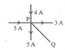
View SolutionFive current carrying conductor meet at a point P. What is the magnitude and direction of the current in the fifth conductor ?
View Solution
Knowledge Check
A current flows in a conductor from east to west. The direction of the magnetic field at a points above the conductor is
ATowards northBTowards southCTowards eastDTowards westThe magnetic field near a current carrying conductor is given by
ACoulomb’s lawBLenz’ lawCBiot-savart’s lawDKirchoff’s lawIn a coaxial, straght cable, the central conductor and the outer conductor carry equal currents in opposite directions.The magnetic field is non-zero.
 Aoutside the cableBinside the inner conductor except axis of the conductorCall the point inside the outer conductor and outside inner conductorDonly on axis of conductors
If a straight conductor is held normal to this page and current is flowing into the page, what is the direction of the electromagnetic field produced ?
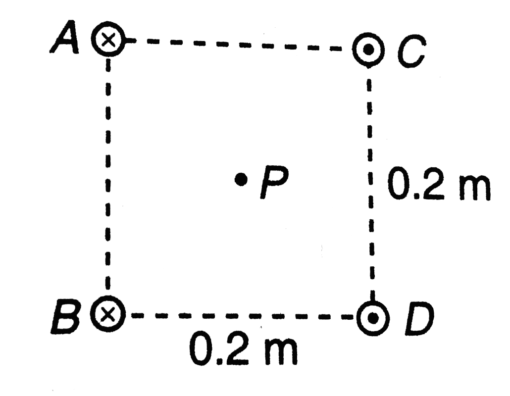
View SolutionFour long, parallel conductors carry equal currents of 5.0. The direction of the currents is into the pge at points. A and B and out of the page at C and D. Calculate the magnitude and directionof the mgnetic field at point P, located at the centre of the square.
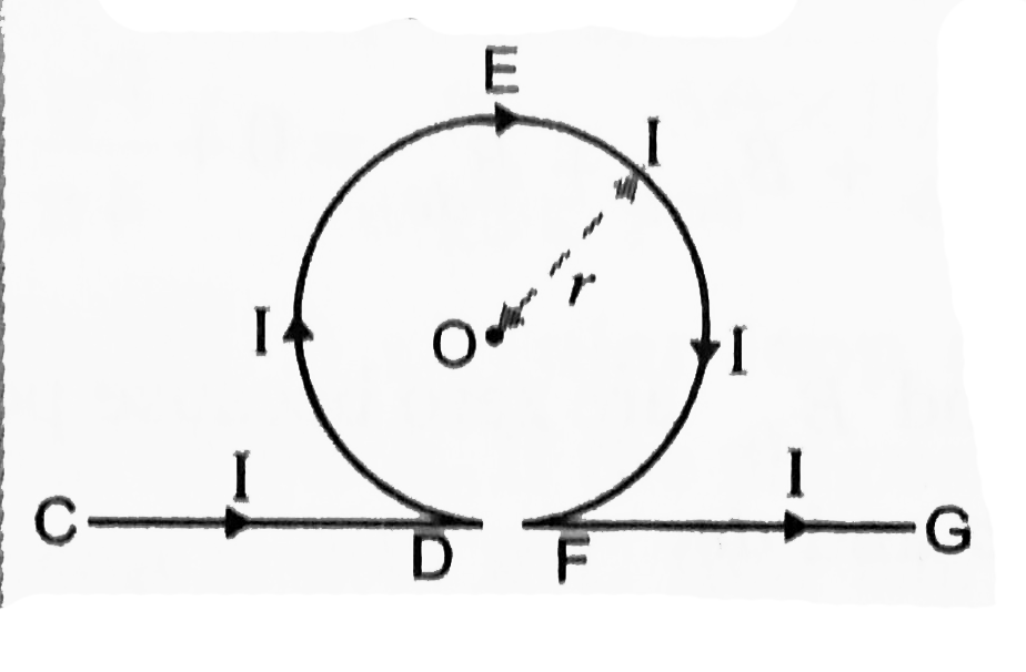
View SolutionIf a long horizontal conductor is bent as shown in figure and a current I is passed in it, find the magnitude and direction of magnetic field induction at the centre of circular part.
View SolutionIn a coaxial, straight cable, the central conductor and the outer conductor carry equal currents in opposite directions. The magnetic field is zero.
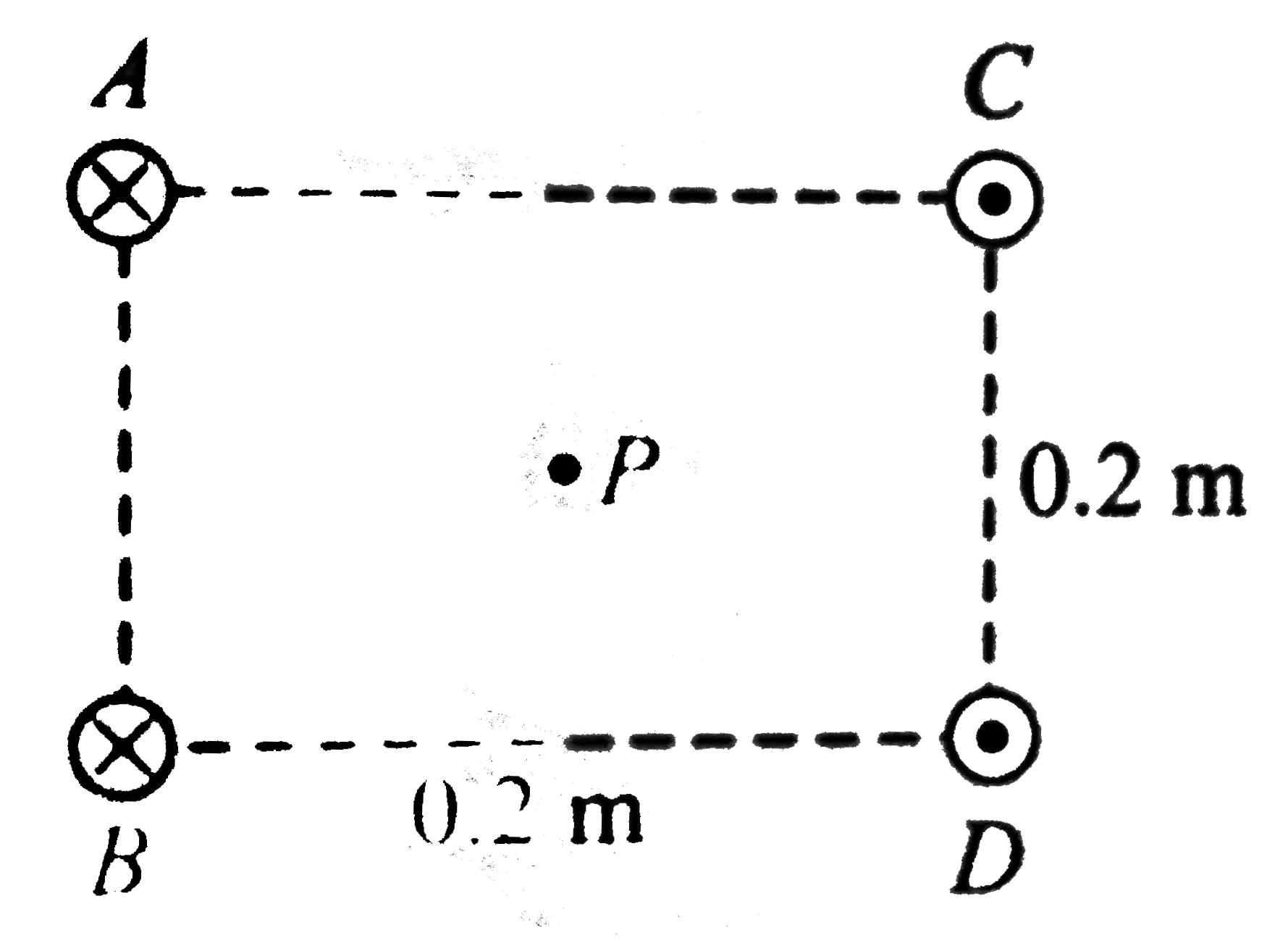
View SolutionFour long, parallel conductors carry equal currents of 5.0A. The direction of the currents is into the page at point A and B and out of the page at C and D. Calculate the magnetic and direction of the magnetic field at point P, located at the centre of the square.
View Solution