One 2 ohm resistor is connected in series with an inductor of reactance 1Ω to a 5 V (rms ) A C source . Find the average power dissipated in the circuit .
To solve the problem, we need to find the average power dissipated in a circuit consisting of a resistor and an inductor connected in series to an AC voltage source. Here are the steps to find the solution:
Step 1: Identify the given values
- Resistance (R) = 2 ohms
- Inductive reactance (X_L) = 1 ohm
- RMS voltage (V_rms) = 5 V
Step 2: Calculate the impedance (Z) of the circuit
The impedance in a series circuit with resistance and inductive reactance can be calculated using the formula:
Z=√R2+X2L
Substituting the values:
Z=√(2)2+(1)2=√4+1=√5 ohms
Step 3: Calculate the RMS current (I_rms)
Using Ohm's law for AC circuits, the RMS current can be calculated as:
Irms=VrmsZ
Substituting the values:
Irms=5√5=√5 A
Step 4: Calculate the phase angle (φ)
The phase angle (φ) between the current and the voltage can be calculated using:
cosϕ=RZ
Substituting the values:
cosϕ=2√5
Step 5: Calculate the average power (P)
The average power dissipated in the circuit can be calculated using the formula:
P=Vrms⋅Irms⋅cosϕ
Substituting the values:
P=5⋅√5⋅2√5=5⋅2=10 W
Final Answer
The average power dissipated in the circuit is 10 Watts.
---
- Resistance (R) = 2 ohms
- Inductive reactance (X_L) = 1 ohm
- RMS voltage (V_rms) = 5 V
The impedance in a series circuit with resistance and inductive reactance can be calculated using the formula:
Z=√R2+X2L
Substituting the values:
Z=√(2)2+(1)2=√4+1=√5 ohms
Using Ohm's law for AC circuits, the RMS current can be calculated as:
Irms=VrmsZ
Substituting the values:
Irms=5√5=√5 A
The phase angle (φ) between the current and the voltage can be calculated using:
cosϕ=RZ
Substituting the values:
cosϕ=2√5
The average power dissipated in the circuit can be calculated using the formula:
P=Vrms⋅Irms⋅cosϕ
Substituting the values:
P=5⋅√5⋅2√5=5⋅2=10 W
The average power dissipated in the circuit is 10 Watts.
Topper's Solved these Questions
- ALTERNATING CURRENT BOOK - MODERN PUBLICATIONCHAPTER - ALTERNATING CURRENT EXERCISE - PRACTICE PROBLEMS
67 Videos
- ALTERNATING CURRENT BOOK - MODERN PUBLICATIONCHAPTER - ALTERNATING CURRENT EXERCISE - CONCEPTUAL QUESTIONS
25 Videos
- ATOMS BOOK - MODERN PUBLICATIONCHAPTER - ATOMS EXERCISE - Chapter Practice Test
16 Videos
Similar Questions
A capacitor of capacitance 2 µF and resistor of resistance 12 Ω are connected in series with voltage source V=(195√2)[sin(100rads)t] - The average power dissipated in the circuit will be
View SolutionA choke coil is connected to an AC source. Some power is dissipated in coil. Now a capacitor is connected in series with the coil and source is same, then average power dissipated in the circuit does not changes. If ratio of inductive reactance of coil and capacitive reactance of capacitor is1x then find x
View Solution
Knowledge Check
An inductor of reactance 2Ω and a resistor of 4Ω are connected in series to the terminals of a 12 V (rms ) AC source. The power dissipated in the circuit is
A8 WB12 WC14.4 WD28.8 WA wire of reistance R is connected in series with an inductor of reactance ω L. Then quality factor of RL circuit is
ARωLBωLRCR√R2+ω2L2DωL√R2+ω2L2An inductor of reactance 1 Ω and a resistor of 2 Ω are connected in series to the terminals of a 6 V (rms) a.c. source. The power dissipated in the circuit is
A8 WB12 WC14.4 WD18 W
A 50Ω resistor is connected in series with an inductor of 0.2 H and capacitor with capacitive reactance 40Ω . The combination is further connected to an AC source 180 V , 50 Hz. What will be the phase angle between current and voltage ? Also find the value of rms current in circuit.
View SolutionA series AC circuit contains an inductor (20mH), a capacitor (100μF), a resistor (50Ω) and an AC source of 12V,50Hz. Find the energy dissipated in the circuit in 1000s.
View SolutionA inductor of reactance 1Ω and a resistor of 2Ω are connected in series to the terminals of a 6 V (rms) a.c. source. The power dissipated in the circuit is
View SolutionAn inductor and a resistor are connected in series with an ac source. In this circuit.
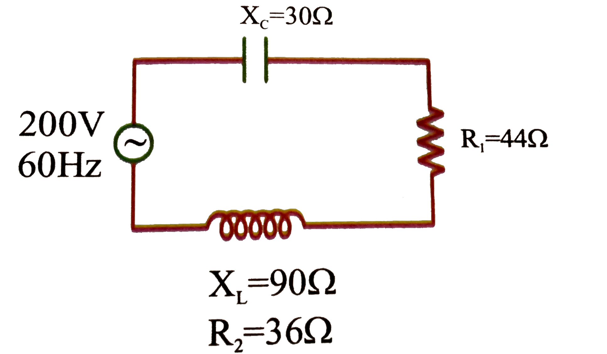
View SolutionA series circuit connected across a 200V,60Hz line consists of a capacitive reactance 30Ω non inductive resistor of 44Ω and a coil of inductive reactance 90Ω and resistance 36Ω as shown in the diagram

The power dissipated in the inductance coil is
View Solution
