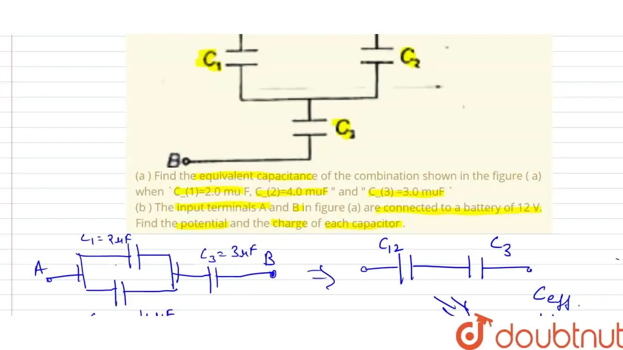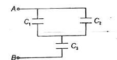
(a ) Find the equivalent capacitance of the combination shown in the figure ( a) when C1=2.0μF,C2=4.0μF and C3=3.0μF
(b ) The input terminals A and B in figure (a) are connected to a battery of 12 V. Find the potential and the charge of each capacitor .
(a) C1and C2 are in parallel hence their equivalent capacitance is
C'=C1+C2=2.0μF+4.0μF=6.0μF
Figure (b) shows the combination of C' and C3 in series. The final equivalent capacitance shown in figure ( c) is given by
1Cεq=1C'+1C3=16.0μF+13.0μF=12.0μF
or Ceq=2.0μF
(b) To find the charge or potential difference , we retrace the path to the original in figure (a) The charge supplied by the battery is
q=CeqV when the inputs are joined to a V-volt battery
=(2.0μF)(12.0V)=24.0μC
The charge on each capacitor in series in figure (b ) is
q3=q=q=24.0μC
So V3=q3C3=24.0μC3.0μF8V
The potential difference across C in figure ( b) is
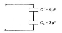
V=qC=24.0μC6.0μF=4V (b) C1andC2 in figure (a) and hence the charges on them are
q1=C1V1=(2.0μF)(4.0V)=8.0μC
and q2=C2V2=(4.0μF)(4.0V)=16.μC
Thus we have V1=V2=4.0V,V3=8V
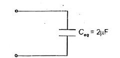
and q1=8.0μC,q2=16.0μC,q3=24.0μC (c) C' and C3 are replaced by Ceq
Related Playlists
- BOOK - AAKASH INSTITUTECHAPTER - ELECTROSTATIC POTENTIAL AND CAPACITANCE EXERCISE - TRY YOURSELF110videos
ELECTROSTATIC POTENTIAL AND CAPACITANCE
- BOOK - AAKASH INSTITUTECHAPTER - ELECTROSTATIC POTENTIAL AND CAPACITANCE EXERCISE - ASSIGNMENT (SECTION-A) Objective Type Questions (Only one answer)47videos
ELECTROSTATIC POTENTIAL AND CAPACITANCE
- BOOK - AAKASH INSTITUTECHAPTER - ELECTROMAGNETIC WAVESEXERCISE - ASSIGNMENT SECTION - D Assertion-Reason Type Questions25videos
ELECTROMAGNETIC WAVES
- BOOK - AAKASH INSTITUTECHAPTER - GRAVITATION EXERCISE - ASSIGNMENT SECTION - D (ASSERTION-REASON TYPE QUESTIONS)16videos
GRAVITATION
Similar Questions
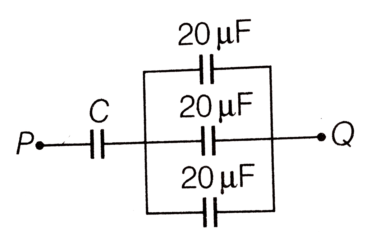
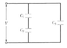
The equivalent capacitance of the combination shown in the figure between P and Q is 30μF, the capacitance of capacitor C isView SolutionIn Fig, 25-26 , find the equivalent capacitance of the combination. C1 is 10.0μF,C2 is 8.00μF, and C3 is 4.00μF
 View Solution
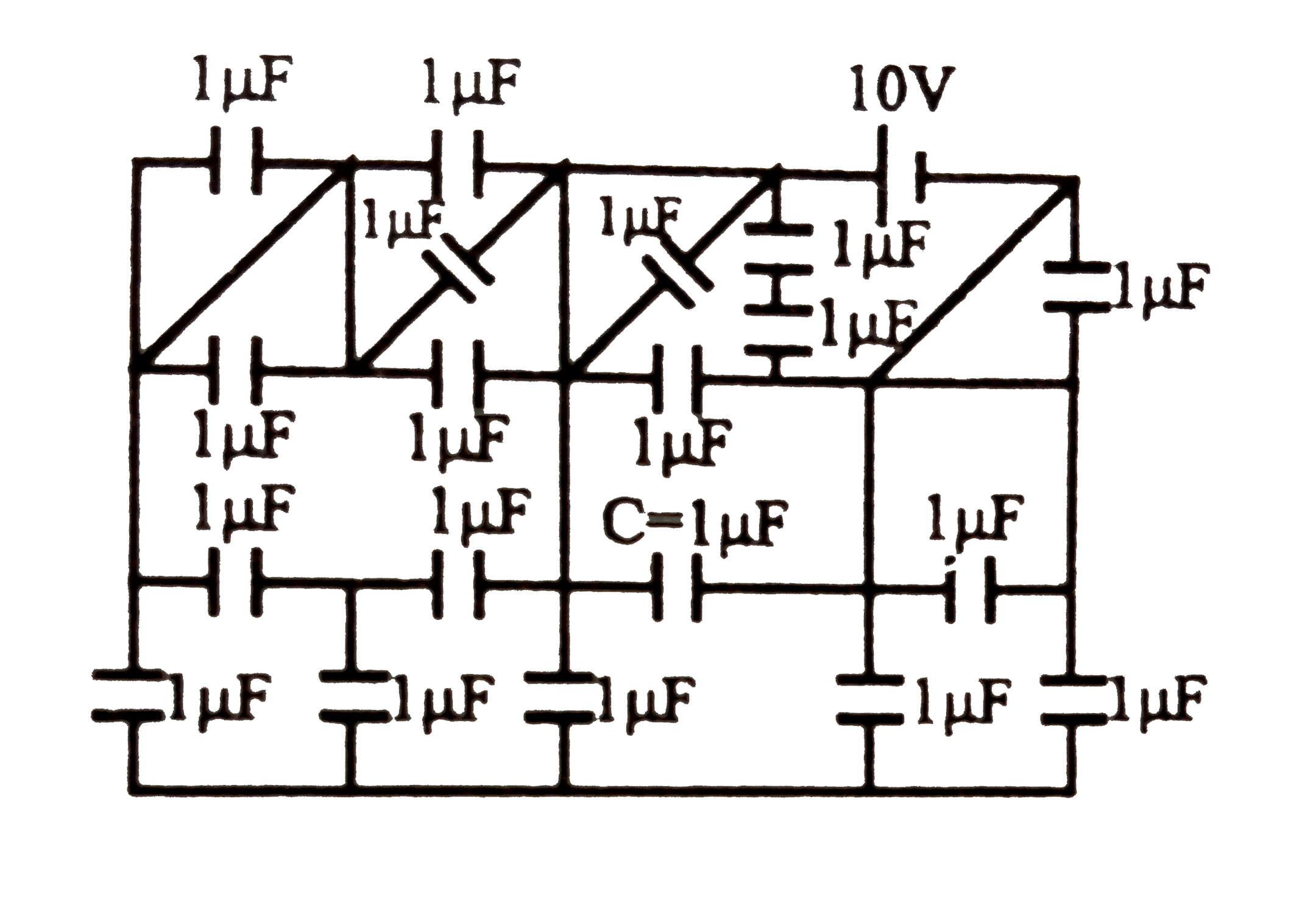
Find the charge on the capacitor C=1μF in the circuit shown in the figure.
 View Solution
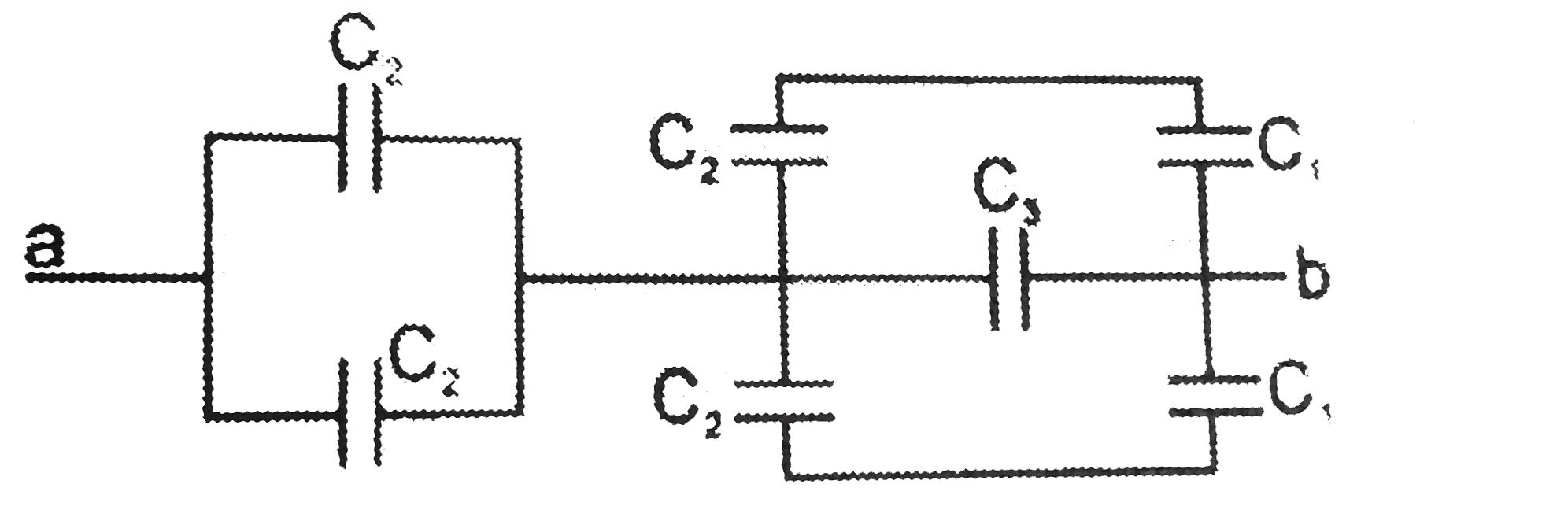
A combination arrangement of the capacitors is shown in the figure
(i) C1=3μF,C2=6μF and C3=2μF then equivalent capacitance between 'a' and 'b' is :
 View Solution
Find the charges on the three capacitors connected to a battery as shown in figure. Take C1=2.0μF,C2,=4.0μF,C3=6.0μF and V =10 volt
 View Solution
In the circuit shown the capacitors are C1=15μF,C2=10μFandC3=25μF. Find
the charge on each capacitor andView SolutionIn the circuit shown the capacitors are C1=15μF,C2=10μFandC3=25μF. Find
the equivalent capacitance of the circuit.View SolutionThe equivalent capacitance of the combination between A and B in the given figure is 4μF .
Calculate charge on each capacitor if a 12 V battery is connected across terminals A and B .
 View Solution
Three identical capacitors C1,C2 and C3 of capacitance 6μF each are connected to a 12 V battery as shown in Fig
charge on each capacitorView SolutionFind the equivalent capacitance for the combination of capacitances shown in fig.25-10a, across which potential difference V is applied . Assume
(a) C1=12.0μF,C2=5.30μFandC3=4.50μF
(b) The potential difference applied to the input terminals in fig.25-10a is V=12.5V What is the charge on C1?View Solution

