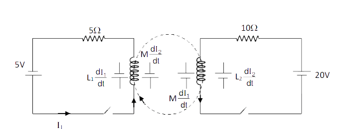
The inductors of the two LR circuits are placed next to each other , as shown in the figure . The values of the self-inductance of the inductors , resistances , mutual - inductance and applied voltages are specified in the given circuit . After both the switches are closed simultaneously , the total work done by the batteries against the induced EMF in the inductors by the time the currents react their steady state values is __________m]
![The inductors of the two LR circuits are placed next to each other , as shown in the figure . The values of the self-inductance of the inductors , resistances , mutual - inductance and applied voltages are specified in the given circuit . After both the switches are closed simultaneously , the total work done by the batteries against the induced EMF in the inductors by the time the currents react their steady state values is m]](https://d10lpgp6xz60nq.cloudfront.net/physics_images/JA_20_P2_PHY_17_Q01.png)
Video Solution
Text Solution
The correct Answer is:55 or 35

ε1=L1di1dt+Mdi2dt
dW1=ε1i1dt
=L1(di1)i1+M(di2)i1
dW2=L2(di2)i2+M(di1)i2
dW1+dW2=L1i1(di1)+L2i2(di2)+Md(i1.i2)
W=12L1i22+12L2i21+M1i2
=55mJ
|
Topper's Solved these Questions
Similar Questions
Knowledge Check
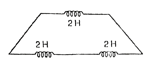
Three pure inductors each of 2H are connected as shown in the figure. The equivalent inductance of the circuit is
 A8H/6B6HC2HDnone of these
Two pure inductors each of self inductance L are connected in series, the net inductance is
A2LBLCL/2DL/4In an inductor, the current / varies with time to l=5A+16.(A/s)t. If-induced emf in the induct is 5 mV, the self inductance of the inductor is
A3.75X10−3HB3.75x10−4HC3.125x10−3HD3.125x10−4H
Pure inductors each of inductance 3 H are connected as shown in figure. The equivalent inductance of the circuit is

View SolutionTwo electric circuits are placed near one another. Each circuit has self inductance Must there be a mutual inductance.
View SolutionQuestions based on Self inductance| Inductors and RL circuits
View SolutionThe current in a 4.0 mH inductor vaires in time as shown in the figure. The corresponding graph of the self induced emf across the inductor over the time interval t=0 to t=12.0 ms is

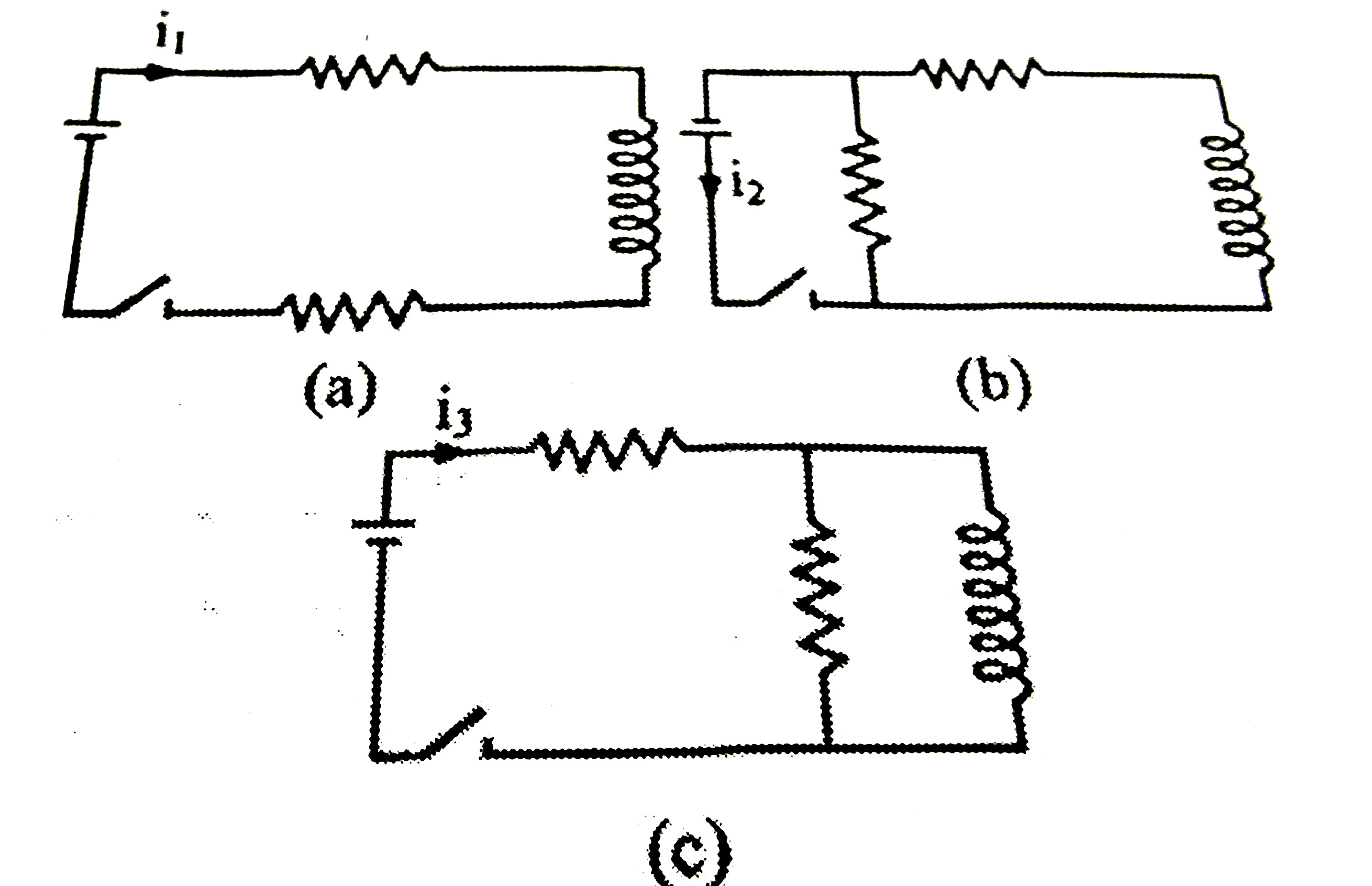
View SolutionThe figure shows three circuits with identical batteries, inductors and resistance, Rank the circuits according to the currents through the battery just after the switch is closed, greatest first :

View Solution