A cell of emf ε and internal resistance r is connected across a variable load resistance R. The graph drawn between its terminal voltage and resistance R is Solution in Telugu
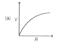
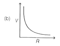
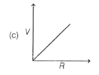
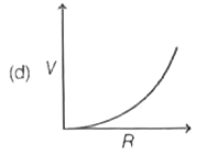
The correct Answer is:A
According to the question, circuit diagram of a cell is given below,
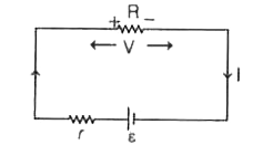
As, Ir=E−V⇒VRr=E−V
⇒V[1+rR]=E⇒V=ER+r.R
General equation of a straight line passing through the origin,
y = mx
Here, y = V, m=ER+r = slope of the line and x = R
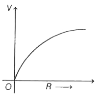
As this line is passing through the origin and has a slope which reduces as R increases. Hence, the graph is
Topper's Solved these Questions
- QUESTION PAPER 2019BOOK - TS EAMCET PREVIOUS YEAR PAPERSCHAPTER - QUESTION PAPER 2019EXERCISE - Physics
80 Videos
- TS EAMCET ENGINEERING ENTRANCE EXAM QUESTION PAPER (2018)BOOK - TS EAMCET PREVIOUS YEAR PAPERSCHAPTER - TS EAMCET ENGINEERING ENTRANCE EXAM QUESTION PAPER (2018)EXERCISE - PHYSICS
40 Videos
Similar Questions
Albert Einstein was confermed with the Nobel prize in physics for his work on
View SolutionChoose the incorrect statement from the following
View Solution2A cell having an emf epsilon and internal resistance r is connected across a variable external resistance R . As the resistance R is increased, the plot of potential difference V across R is given by
View SolutionA resistance R is connected across a cell of emf epsilon and internal resistance r. A potentiometer now measures the potential difference between the terminals of the cell is V. Write the expression for r in terms of epsilon , V and R .
View SolutionA cell of emf epsilon and internal resistance r is connected across a variable load resistance R . It is found that when R = 4 Omega the current is 1A and when R is increased to 9 Omega , the current reduces to 0.5A . Find the value of the emf epsilon and internal resistance r
View SolutionA cell of emf epsilon and internal resistance r is connected across a load resistance R (i) Find the maximum power delivered at the load ? (ii) Draw the power (P ) vs load resistance ( R ) graph.
View SolutionA cell of emf epsilon and internal resistance (r) is connected in series with an external resistance (nr) then the ratio of the terminal potential difference to emf is:
View SolutionA cell of emf E and internal resistance r is connected to a variable external resistor R. the graph which gives the terminal voltage of cell V with respect to R is
View Solution.A cell of emf E and internal resistance r is connected across a variable resistor. Plot a graph showing variation of terminal voltage V of cell versus the current.
View SolutionA cell of emf (E) and internal resistance r is connected across a variable external resistance . R. The graph of terminal potential difference V as a function of R is
View SolutionA resistance R is connected across a cell of emf ε and internal resistance r. A potentiometer now measures the potential difference between the terminals of the cell is V. Write the expression for r in terms of ε, V and R.
View SolutionA cell of emf epsilon and internal resistance r is connected across a variable resistor R. Plot a graph showing variation of terminal voltage V of the cell versus the current I. Using the plot, show how the emf of the cell and its internal resistance can be determined.
View SolutionA battery of emf (epsilon) and internal resistance r is connected across a load resistance R_L The plot between output power and load resistance is shown in the figure. value of emf (epsilon) and internal resistance respectively will be
View SolutionA battery of emf epsilon and internal resistance r is connected across a load resistance R_L . The plot between output power and load resistance is shown in the figure The value of emf epsilon and internal resistance r respectively will be
View Solution2A cell having an emf epsilon and internal resistance r is connected across a variable external resistance R . As the resistance R is increased, the plot of potential difference V across R is given by
View Solution
