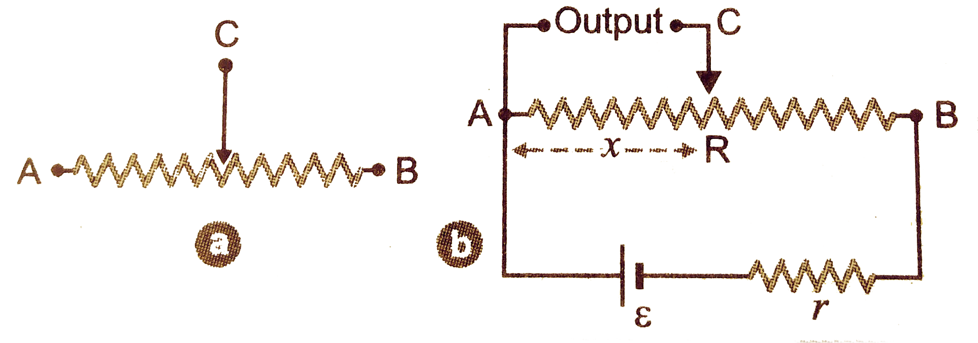
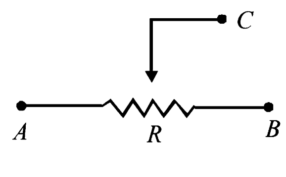
Schematic of a rheostat is shown in the figure. Connect a battery to it so that the rheostat acts as a potential divider.Specify which are the input and output terminals

The output terminals are [AC] or [B.C]

Topper's Solved these Questions
- CURRENT ELECTRICITYBook:FIITJEEChapter:CURRENT ELECTRICITYExercise:ASSIGNMENT PROBLEMS (SUBJECTIVE)(Level-II//III)
Explore 14 Videos
- CURRENT ELECTRICITYBook:FIITJEEChapter:CURRENT ELECTRICITYExercise:ASSIGNMENT PROBLEMS (OBJECTIVE)(Level-1)
Explore 45 Videos
- CURRENT ELECTRICITYBook:FIITJEEChapter:CURRENT ELECTRICITYExercise:Matrix Match type
Explore 3 Videos
- COLLISION Book:FIITJEEChapter:COLLISION Exercise:(NUMERICAL BASED QUESTIONS)
Explore 4 Videos
- ELASTICITY AND WAVES Book:FIITJEEChapter:ELASTICITY AND WAVES Exercise:Assignment Problems (Objective) Level-II
Explore 15 Videos
Similar Questions
Knowledge Check
Three capacitors are connected as shown in the figure . The potential at point O is equal to
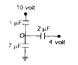 A1.4 voltB4.7 voltCZeroD1.8 volt
Four resistors are connected as shown in the figure. A 6 V battery of negligible resistance is connected across terminal battery of negligible resistance A and C. The potential difference across terminal B and D will be
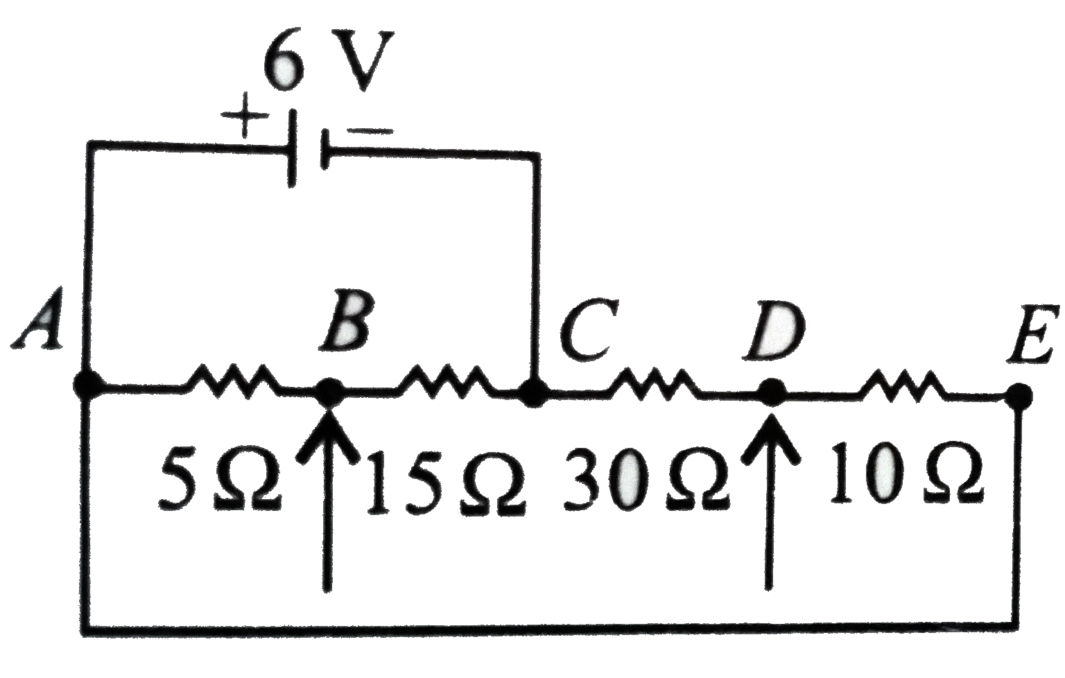 AZeroB1.5 VC2VD3V
Three batteries are connected as shown in the figure.
Then the total emf in the circuit is ____ V.
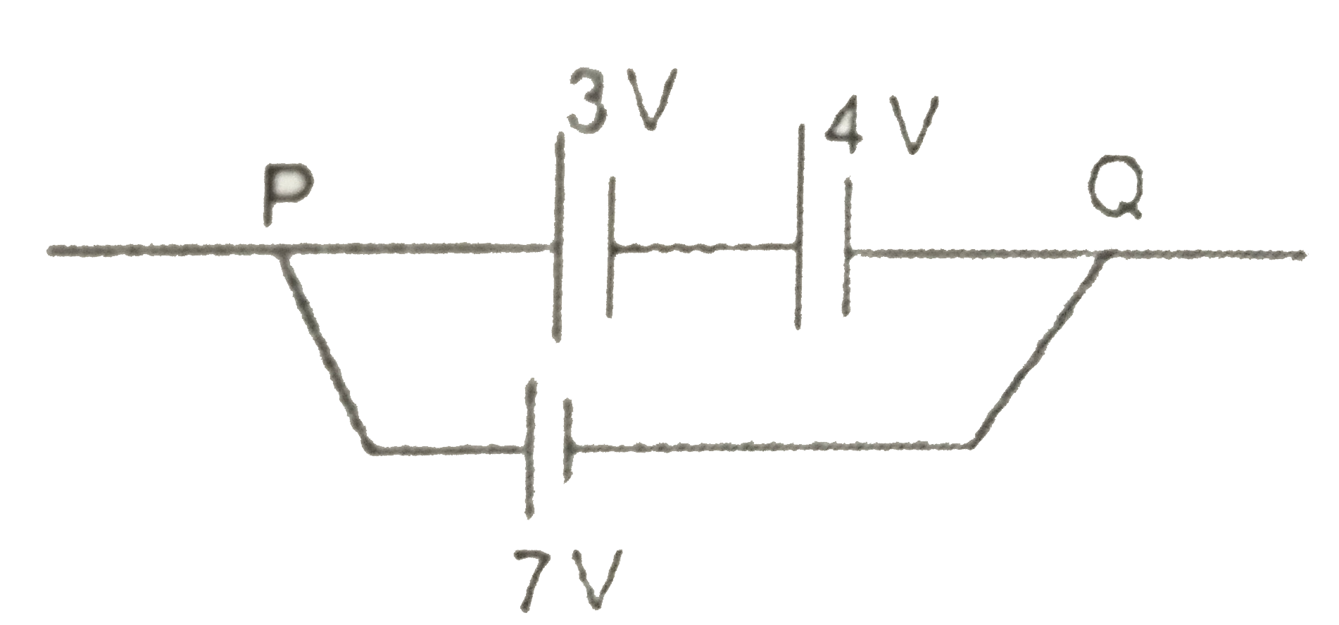 A3B4C7D14
Connect a battery to the terminals and completer the circuit diagram fo that it works as a potential divider meter. Indicate the output terminals also.
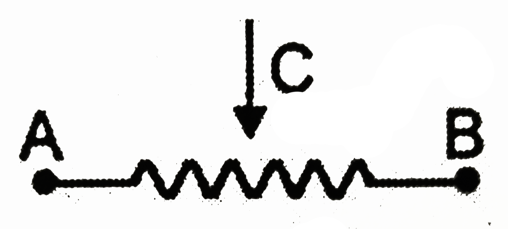
View SolutionHow a battery is to be connected so that the shown rheostat will behave like a potential divider? Also indicate the points about which output can be taken.
 .
.
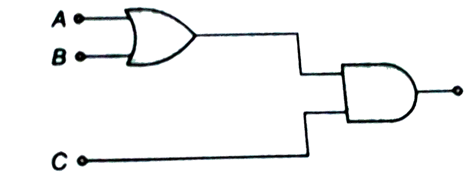
View SolutionTo get an output 1 from the circuit shown in the figure, the input must be
View SolutionThree batteries are connected as shown in the figure.
Then the total emf in the circuit is ____ V.

View SolutionA parallel plate capacitor has two layers of dielectrons as shown in figure. This capacitor is connected across a battery, then the ratio of potential difference across the dielectric layers is

View Solution


