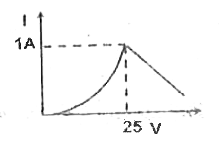
Current-voltage characteristics of two elements A and B are as shown below in Figs. (a) and (b).
(a) 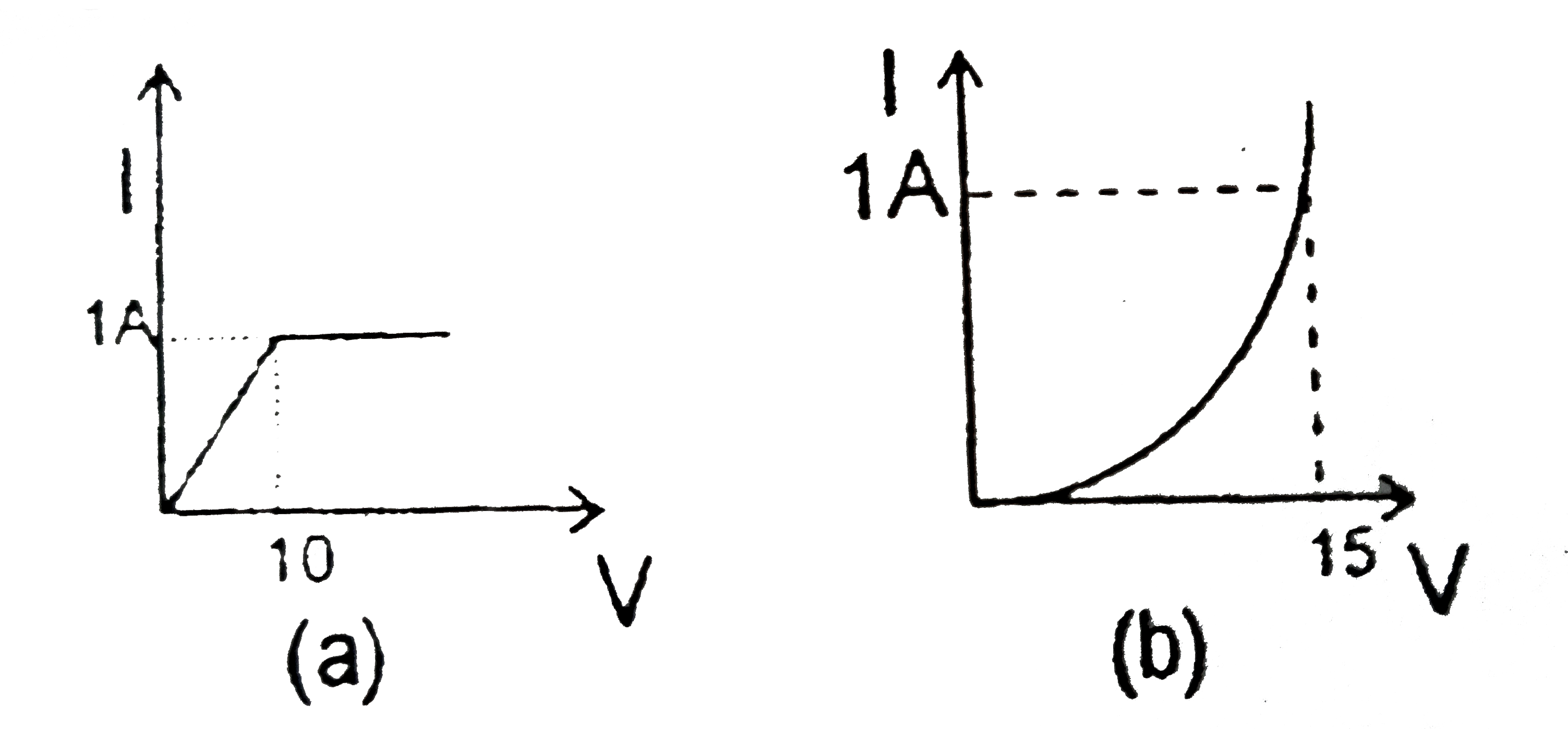
Which of the following graphs represents current voltage characteristics for their series combinations ?
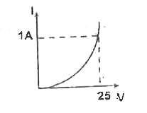
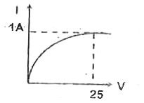
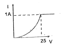
The correct Answer is:C
In the voltage does not increase this current (which is constant at 1 A). This means that the ratio. V/RA = constant and this resistance RA increases linearly with voltage
In element B, the resistance decreases gradually upto 15 V and afterwards the resistance Re increases linearly with voltage.
When both A and B are in series, the current in the circuit will increase non-linearly upto 1 A when the total voltage drop across A and B becomes 10+15=25V Further increase in this voltage does not bring about any change in the current as shown in solution (C). The voltage drop across A will go on increasing while that across B remains fixed at 15 V. Hence (C) is correct
Topper's Solved these Questions
- CURRENT ELECTRICITYBook:FIITJEEChapter:CURRENT ELECTRICITYExercise:Exercise
Explore 9 Videos
- CURRENT ELECTRICITYBook:FIITJEEChapter:CURRENT ELECTRICITYExercise:Comprehension Based Type-1
Explore 3 Videos
- CURRENT ELECTRICITYBook:FIITJEEChapter:CURRENT ELECTRICITYExercise:SOLVED PROBLEMS (SUBJECTIVE)
Explore 10 Videos
- COLLISION Book:FIITJEEChapter:COLLISION Exercise:(NUMERICAL BASED QUESTIONS)
Explore 4 Videos
- ELASTICITY AND WAVES Book:FIITJEEChapter:ELASTICITY AND WAVES Exercise:Assignment Problems (Objective) Level-II
Explore 15 Videos
Similar Questions
Knowledge Check
Current-voltage characteristics of two elements A and B are as shown below in Figs. (a) and (b).
(a)
Which of the following graphs represents current voltage characteristics for their series combinations ?A B
B C
C D
D
Which of the following represents the value of voltage and current at that instant?
AVmsinωt,imsinωtBVmcosωt,imcosωtC−Vmsinωt,−imsinωtD−Vmcosωt,−imcosωtWhich of the shown graphs may represent the reactance of a series L-C combination?
A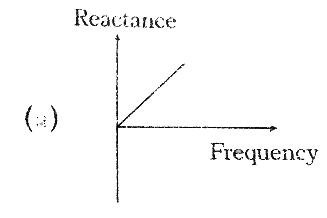 B
B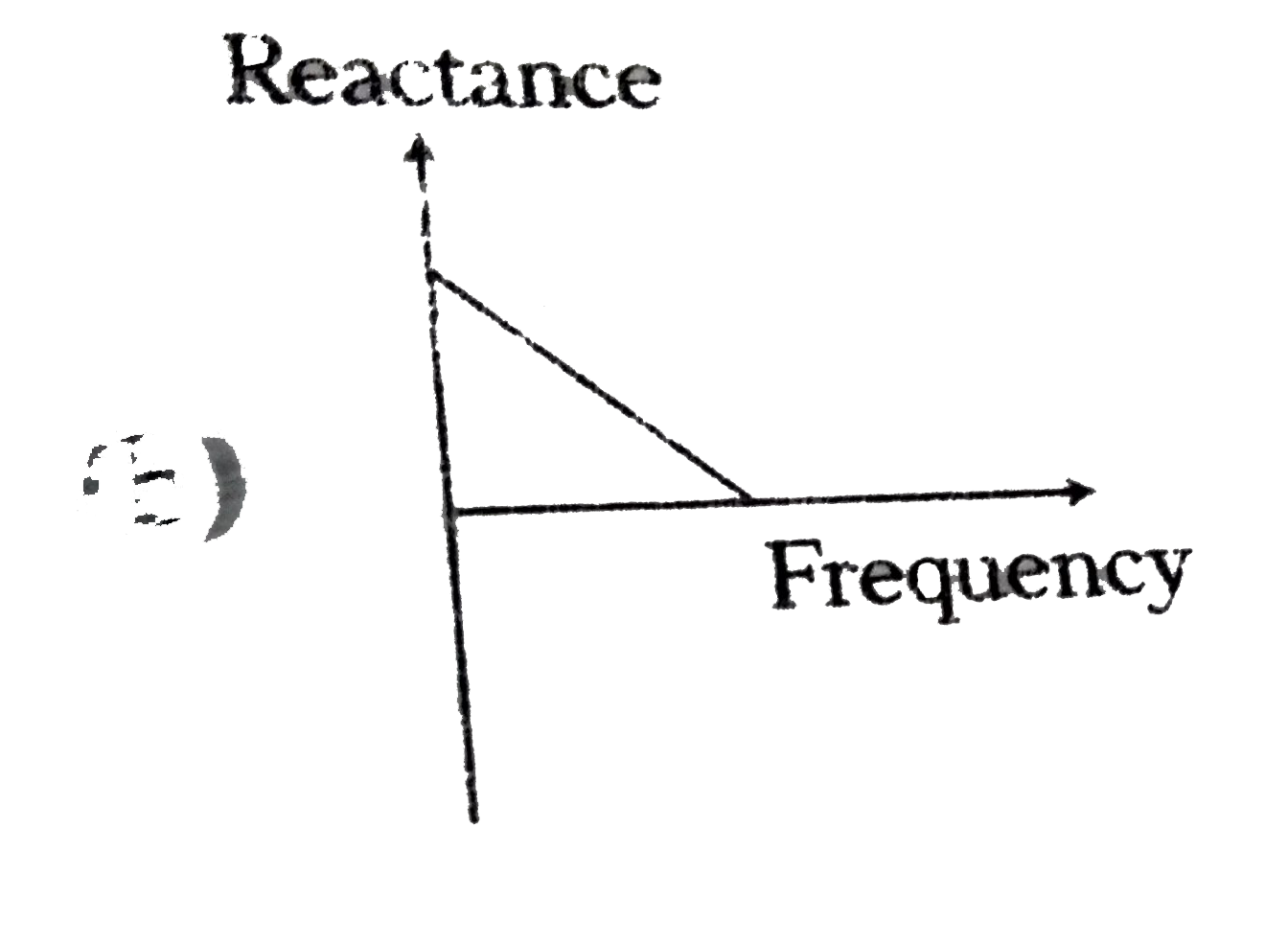 C
C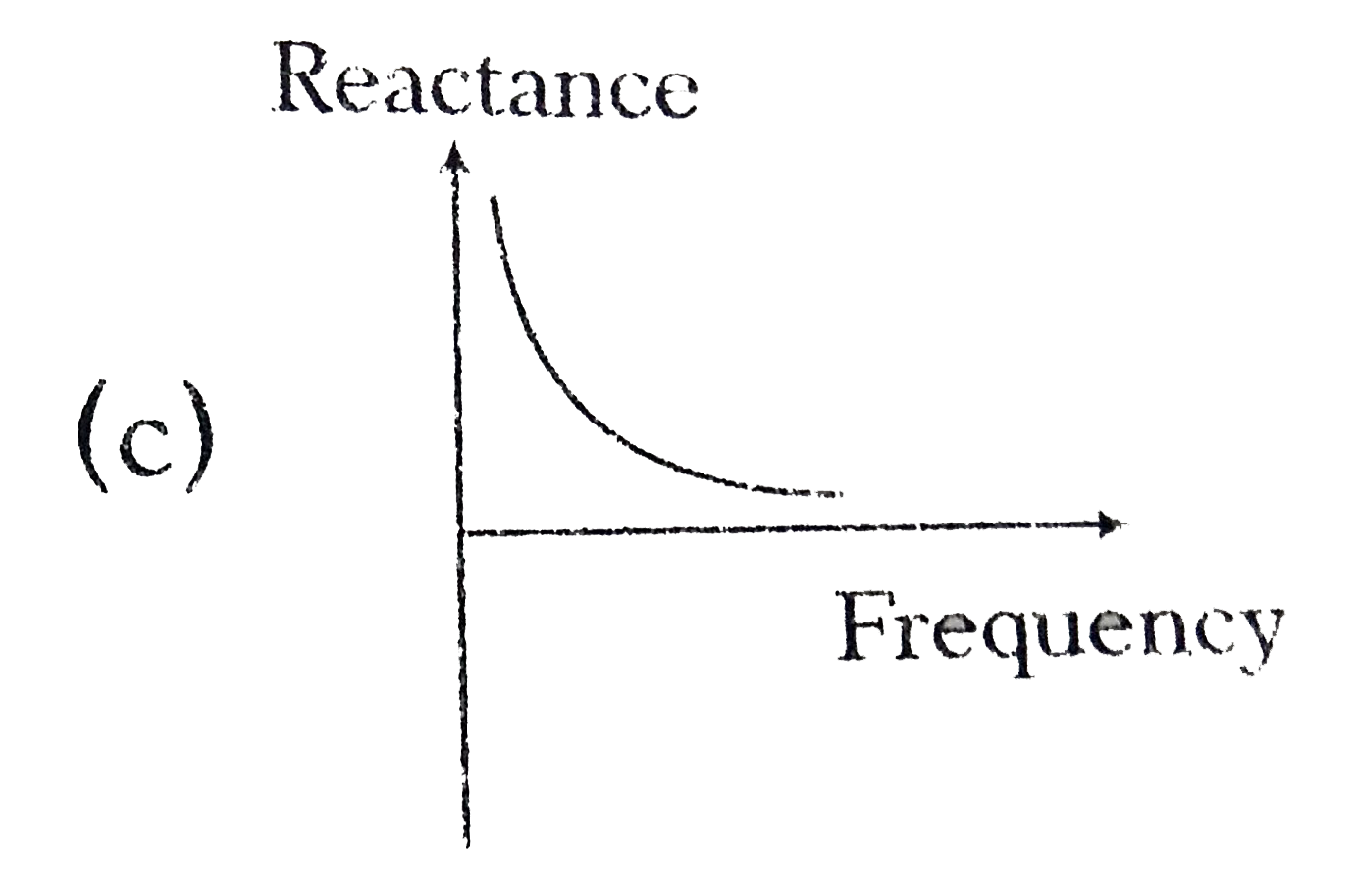 D
D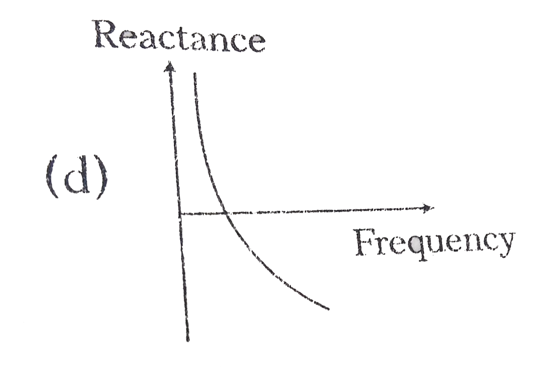
Consider a box with three terminals on top of it as shown in figure.
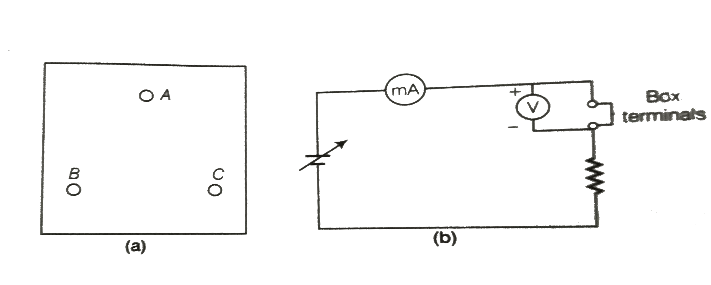
Three components namely, two germanium diodes and one resistor are connected across these three terminals in some arrangement
A student performs an experiment in which any two of these three terminals are connected in the circuit shown in figure.
The student obtains graphs of current-voltage characteristics for unknown combination of components between the two terminals connected in the circuit. The graphs are
(i) When A is positive and B is negative
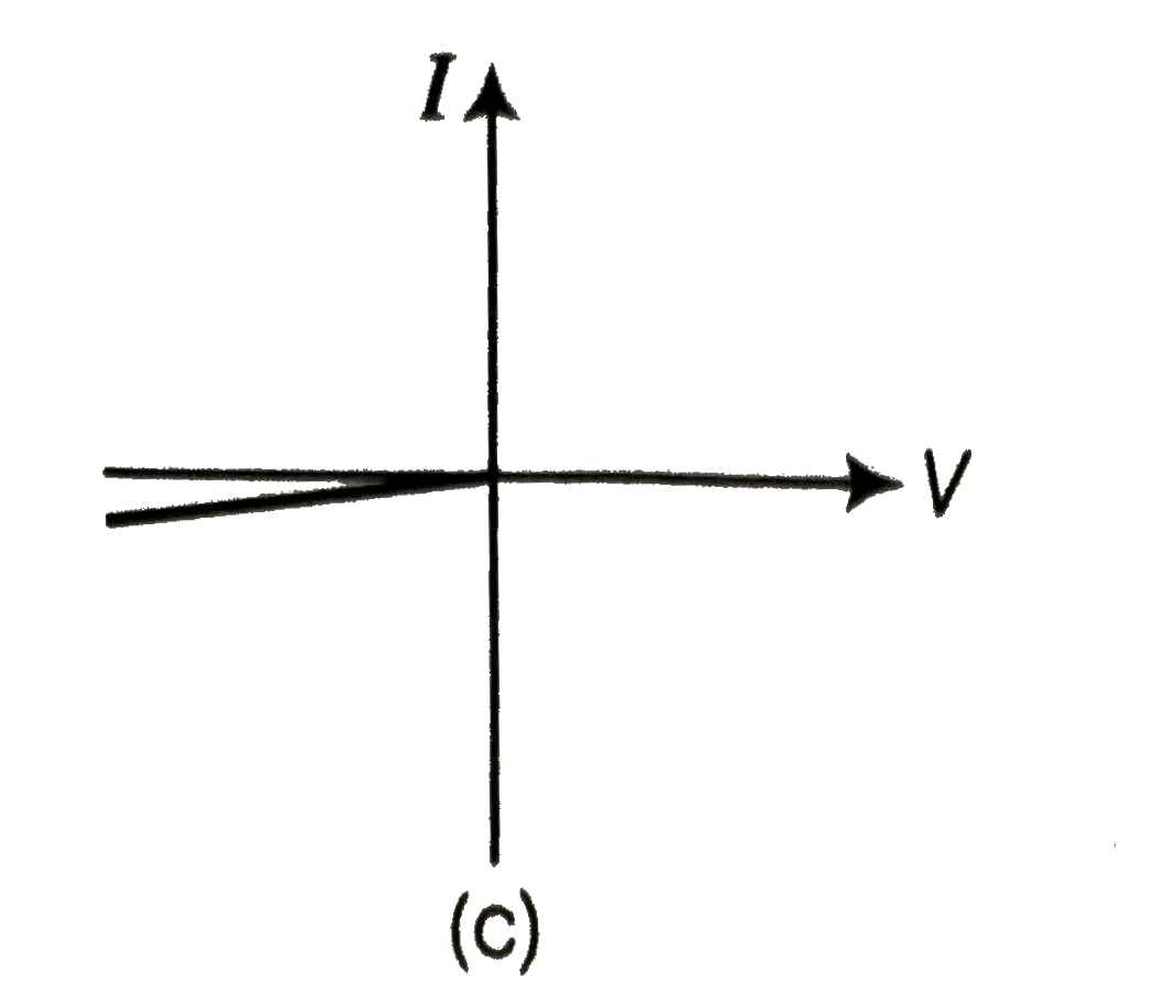
(ii) When A is negative and B is positive
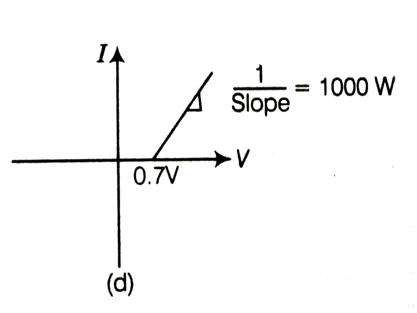
(iii) When B is negative and C is positve
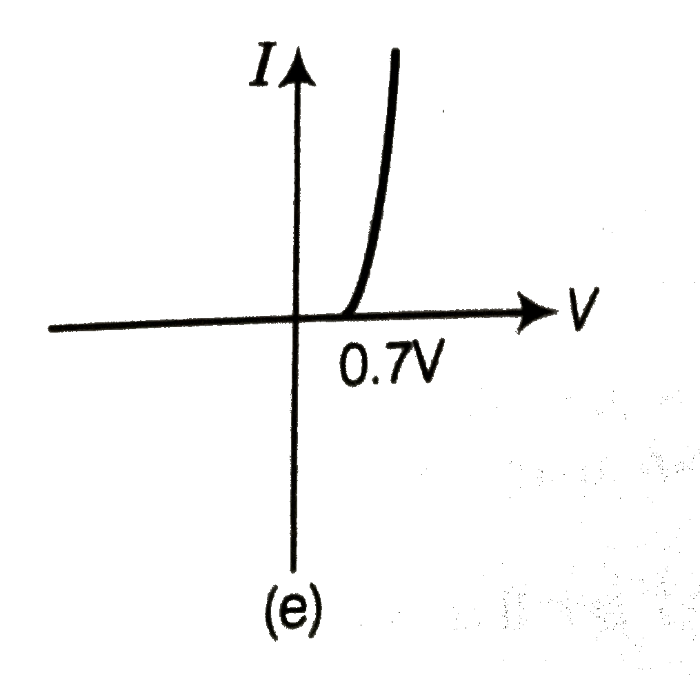
(iv) When B is positive and C is neagtive
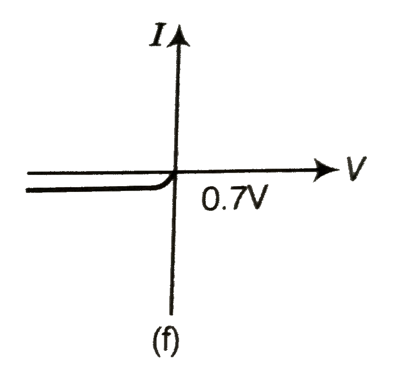
(v) When A is positive and C is negative
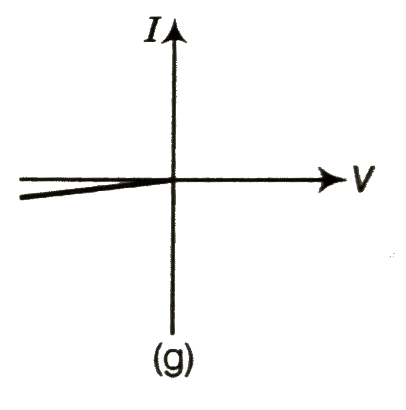
(vi) When A is negative and C is positive
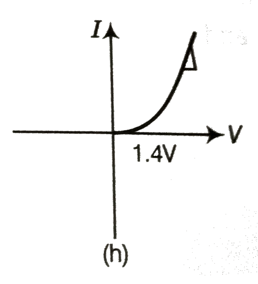
From these graphs of current − voltage characteristic shown in fig. (c) to (h) determine the arrangement of components between A, B and C.
View SolutionThe point representing the cut off grid voltage on the mutual characteristic of triode is
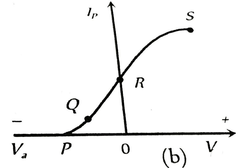
View SolutionThe voltage across a pure inductor is represented by the following diagram. Which one of the following diagrams will represent the current
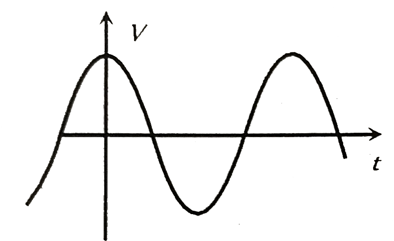
View SolutionThe graph between the current and the time for an inductance coil is shown below. Which of the following graph show the voltage-time variation-
View SolutionThe phase difference between the current and voltage of LCR circuit in series combination at resonance is
View Solution

