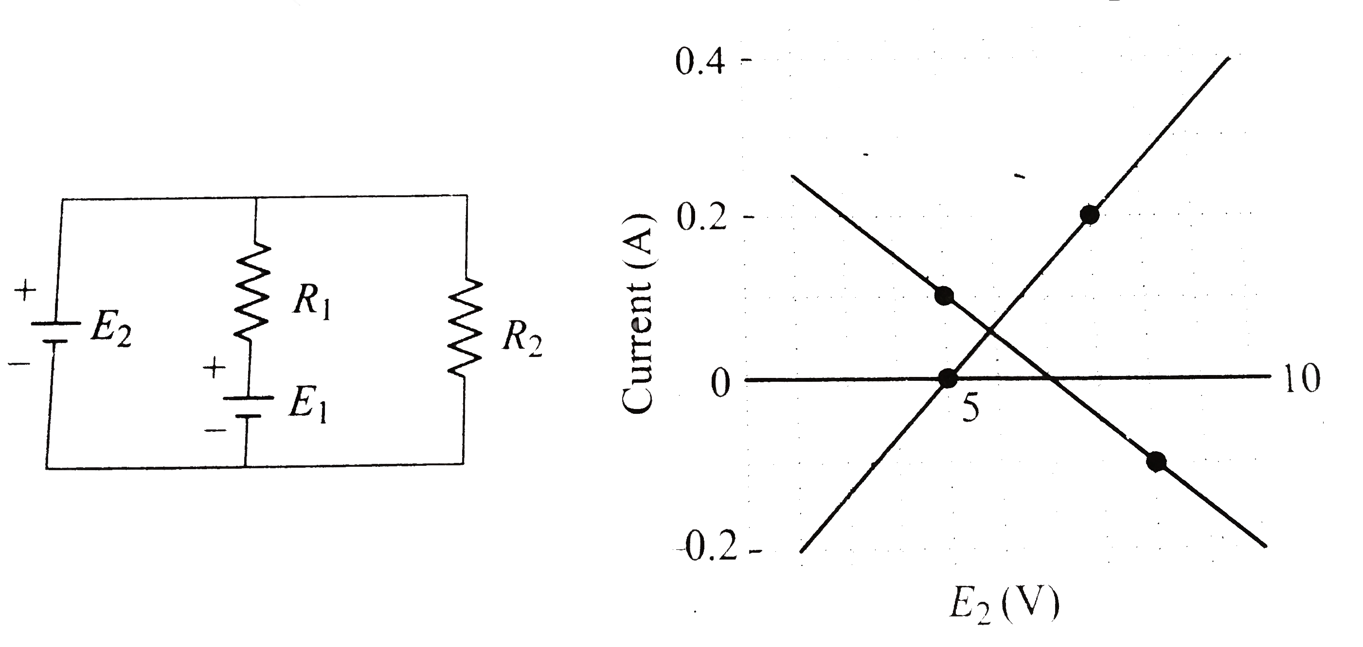
In the circuit given below, both batteries are ideal. Emf of battery 1 has a fixed value, but emf of battery 2 can be varied between 1.0 V and 10.0 and 10.0 V. The graph gives the currents through the two batteries as a function of , but are not marked as which plot corresponds to which battery. But for both ploth, current is assumed to be negative when the direction of the current through the cattery is oppositi the direction of that battery's emf. (Direction of emf is from negative to positive)
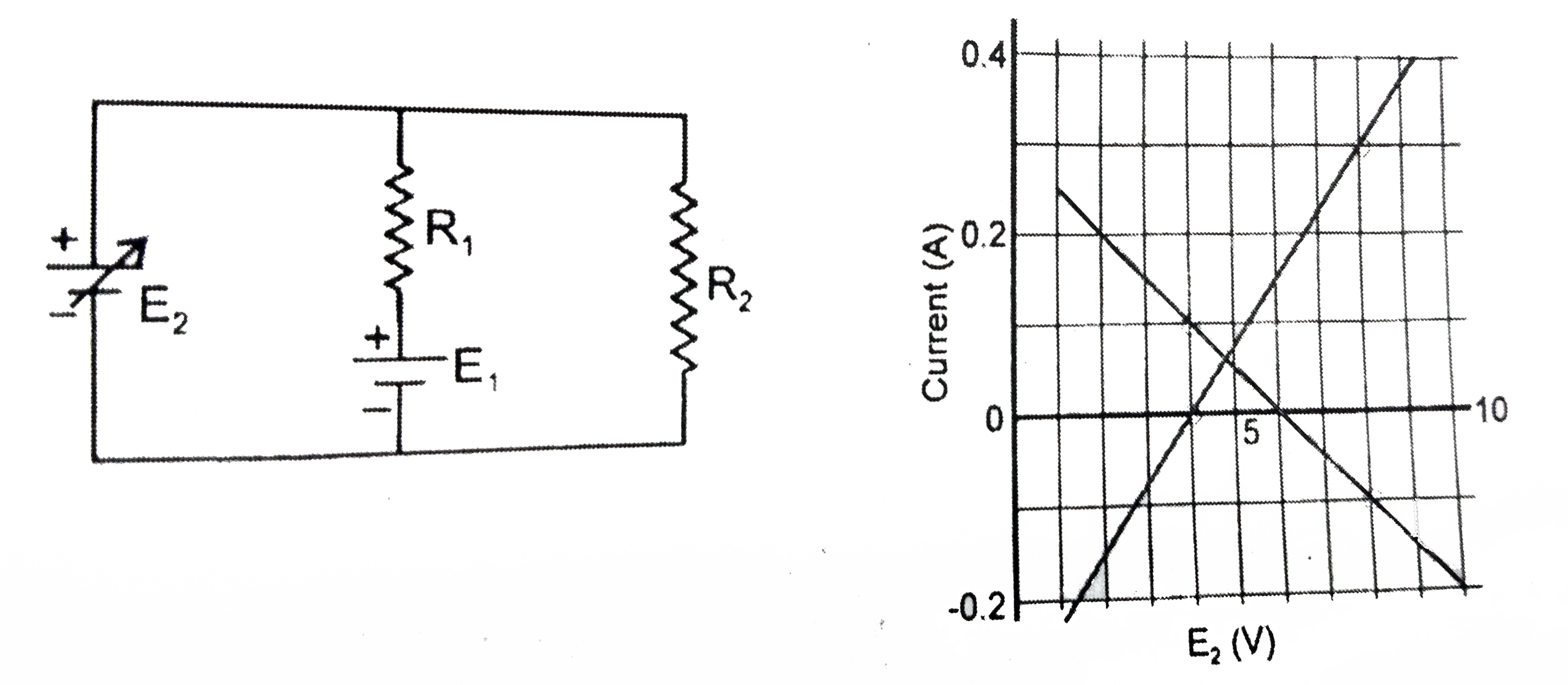
The resistance has value
The correct Answer is:B
Related Playlists
- BOOK - RESONANCECHAPTER - CURRENT ELECTRICITYEXERCISE - Exrcies-3(PART-1)22videos
CURRENT ELECTRICITY
- BOOK - RESONANCECHAPTER - CURRENT ELECTRICITYEXERCISE - Exrcies-3(PART-2)23videos
CURRENT ELECTRICITY
- BOOK - RESONANCECHAPTER - CURRENT ELECTRICITYEXERCISE - Exercise-2 (Part-3)22videos
CURRENT ELECTRICITY
- BOOK - RESONANCECHAPTER - COMMUNICATION SYSTEMSEXERCISE - Exercise 313videos
COMMUNICATION SYSTEMS
- BOOK - RESONANCECHAPTER - DAILY PRACTICE PROBLEMEXERCISE - DPP.No.711videos
DAILY PRACTICE PROBLEM
Knowledge Check
- Question 1 - Select One
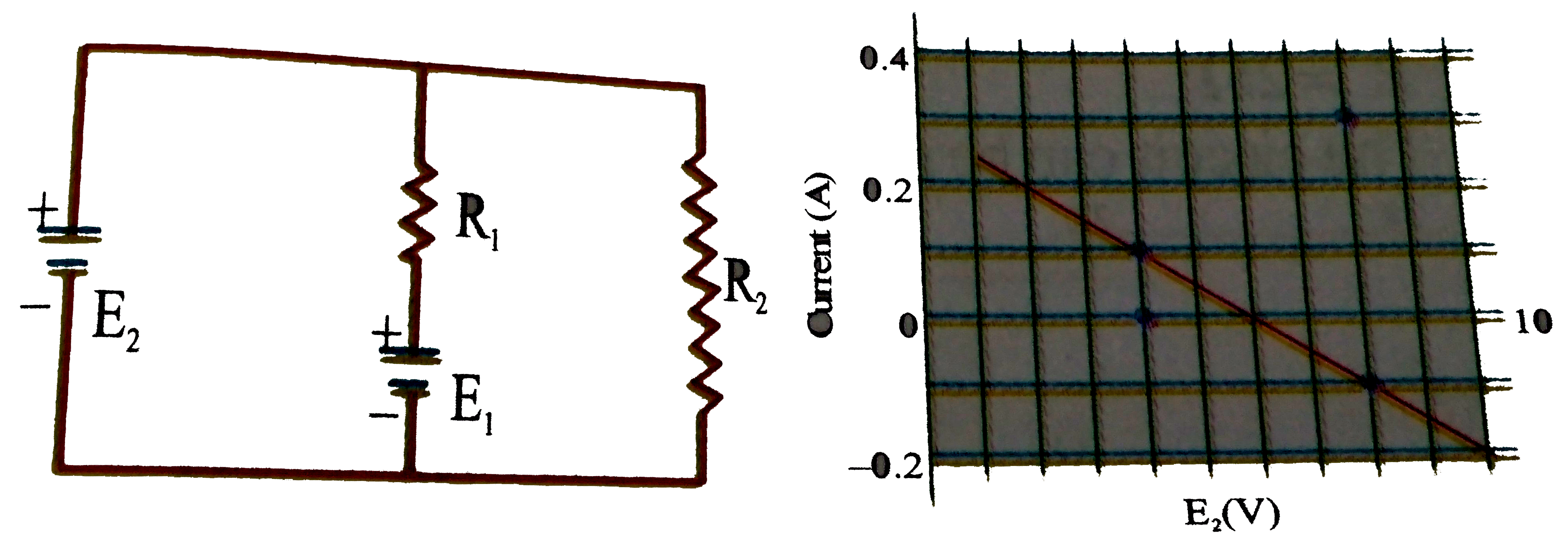
In the circuit givenn below, both batteries are ideal. EMF E1 of battery 1 has a fixed value but emf E2 of battery 2 can be varied between 1.0 V and 10.0 V the graph gives the currents through the two batteries as a function of E2, but are not marked as shown plot corresponds to which battery. but both plots, current is assumed to be negative when the direction of the current through the battery is opposite the direction of that battery's emf. (direction of emf is from negative to positive).
Q. The resistance R1 has valueA10ΩB20ΩC30ΩD40Ω - Question 1 - Select One
In the circuit given in the figure, both batteries are ideal . Emf E1 of battery 1 has a fixed value, but emf E2 of battery 2 can be varied between 1.0Vand10.0V . The graph gives the currents through the two batteries as a function of E2 but are not marked as which plot corresponds to which battery. But for both plots, current is assumed to be negative when the direction of the current through the battery is opposite to the direction of that battery's emf (direction of emf is from negative to positive.)
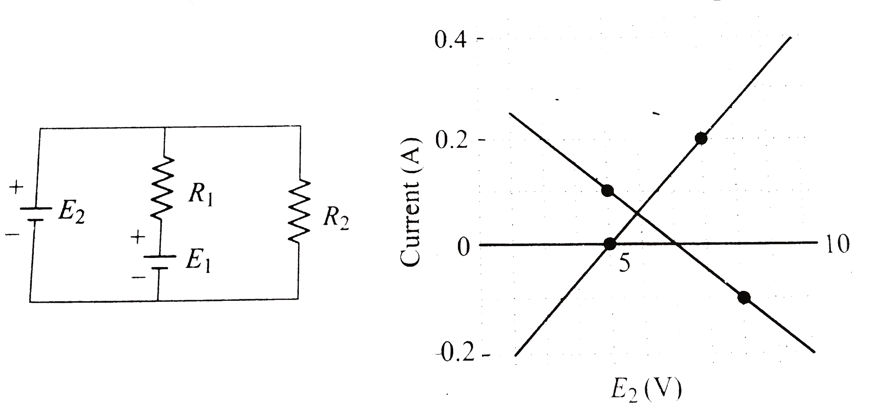
The value of emf E1 isA8 VB6 VC4 VD2 V - Question 1 - Select One
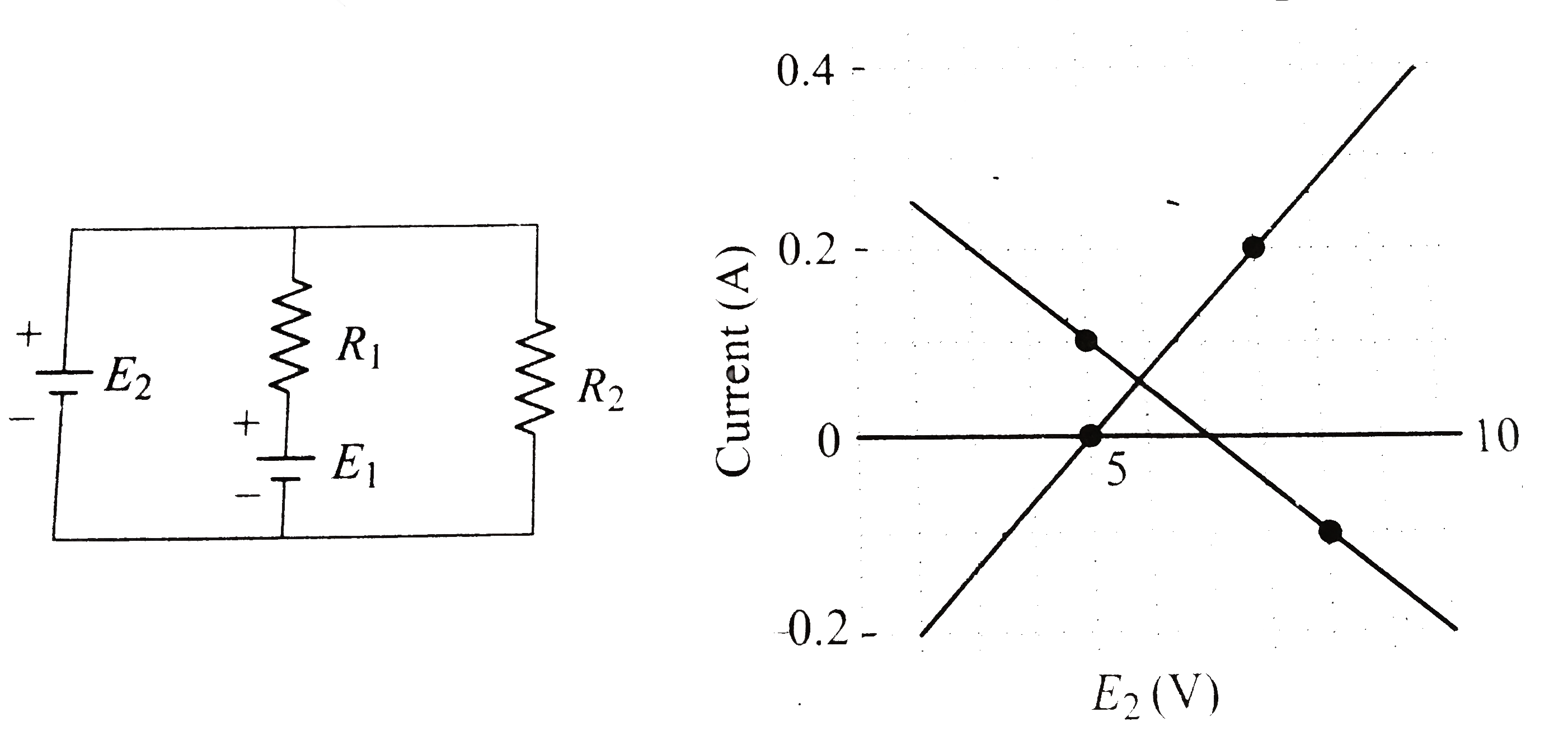
In the circuit given in the figure, both batteries are ideal . Emf E1 of battery 1 has a fixed value, but emf E2 of battery 2 can be varied between 1.0Vand10.0V . The graph gives the currents through the two batteries as a function of E2 but are not marked as which plot corresponds to which battery. But for both plots, current is assumed to be negative when the direction of the current through the battery is opposite to the direction of that battery's emf (direction of emf is from negative to positive.)
 ,
,
The resistance R2 is equal toA10ΩB20ΩC30ΩD40Ω - Question 1 - Select One or More
In the circuit shown, the resistances are given in ohms and the battery is assumed ideal with emf equal to 3.0 V.
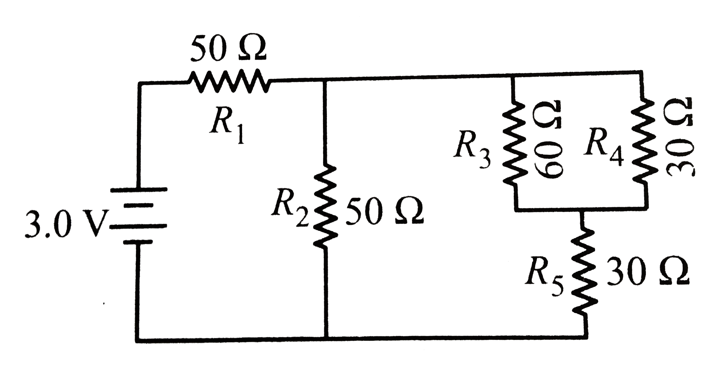 AThe resistor R5 that dissipates maximum power.BThe resistor R1 that dissipates maximum power.CThe potential difference across resistor R3is0.4V.DThe current passing through 3 V battery is 40 mA.
 - Question 1 - Select One
Two batteries of different emf and internal resistances connected in series with each other and with an external load resistor. The current reversed, the current becomes 1.0 A. the ratio of the emf of the two batteries is
A2.5:1B2:1C3:2D1:1
Similar Questions
In the circuit given in the figure, both batteries are ideal . Emf E1 of battery 1 has a fixed value, but emf E2 of battery 2 can be varied between 1.0Vand10.0V . The graph gives the currents through the two batteries as a function of E2 but are not marked as which plot corresponds to which battery. But for both plots, current is assumed to be negative when the direction of the current through the battery is opposite to the direction of that battery's emf (direction of emf is from negative to positive.)

The value of emf E1 isView SolutionIn the circuit given in the figure, both batteries are ideal . Emf E1 of battery 1 has a fixed value, but emf E2 of battery 2 can be varied between 1.0Vand10.0V . The graph gives the currents through the two batteries as a function of E2 but are not marked as which plot corresponds to which battery. But for both plots, current is assumed to be negative when the direction of the current through the battery is opposite to the direction of that battery's emf (direction of emf is from negative to positive.)
 ,
,
The resistance R1 has valueView SolutionIn the circuit given in the figure, both batteries are ideal . Emf E1 of battery 1 has a fixed value, but emf E2 of battery 2 can be varied between 1.0Vand10.0V . The graph gives the currents through the two batteries as a function of E2 but are not marked as which plot corresponds to which battery. But for both plots, current is assumed to be negative when the direction of the current through the battery is opposite to the direction of that battery's emf (direction of emf is from negative to positive.)
 ,
,
The resistance R2 is equal toView Solution3.0 A current passing through Two batteries of different emf and internal resistances connected in series with each other and with an external load resistor. The current reversed, the current becomes 1.0 A. the ratio of the emf of the two batteries is
View SolutionA battery of emf 2 volts and internal resistance 0.1 ohm is being charged with a current of 5 amps.
In what directions will the currents flow inside the battery? What is the potential difference between the two terminal of the battery?View Solution

