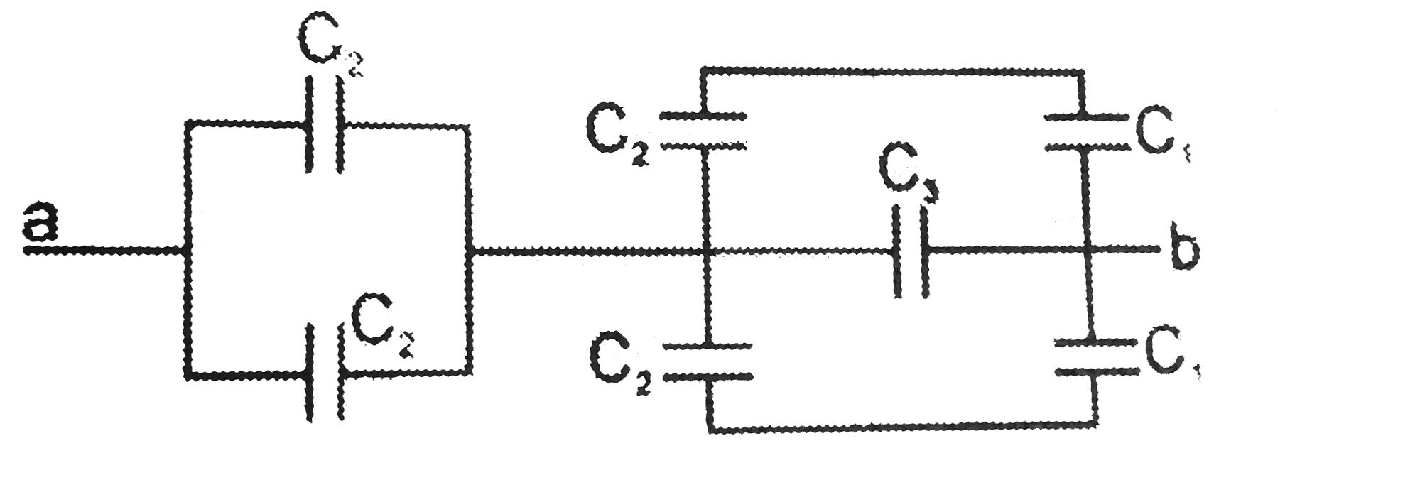
In the arrangement of the capacitor shown in the figure, each C1 capacitor has capacitance of 3μF and each C2 capacitor has capacitance of 2μF then,
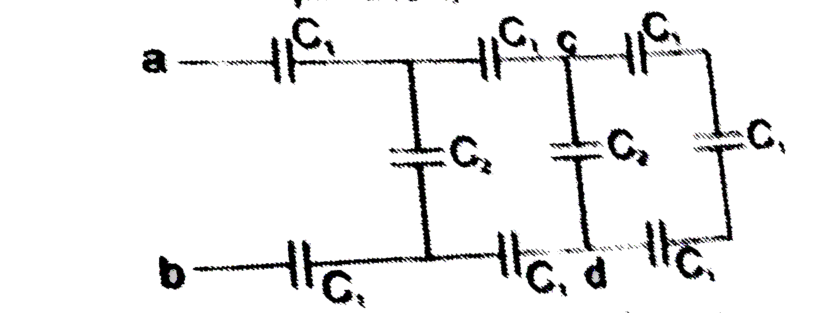
(iii) If Vab=900V, then potential difference across points c and d is :
60 V
100 V
120 V
200 V
The correct Answer is:B
Step by step video, text & image solution for In the arrangement of the capacitor shown in the figure, each C_(1) capacitor has capacitance of 3mu F and each C_(2) capacitor has capacitance of 2mu F then, (iii) If V_(ab)=900 V, then potential difference across points c and d is : by Physics experts to help you in doubts & scoring excellent marks in Class 12 exams.
Updated on:21/07/2023Topper's Solved these Questions
- CAPACITANCEBook:RESONANCEChapter:CAPACITANCEExercise:Exercise - 3
Explore 26 Videos
- CAPACITANCEBook:RESONANCEChapter:CAPACITANCEExercise:High Level Problems
Explore 16 Videos
- CAPACITANCEBook:RESONANCEChapter:CAPACITANCEExercise:Exercise - 1
Explore 79 Videos
- ATOMIC PHYSICSBook:RESONANCEChapter:ATOMIC PHYSICSExercise:Advanved level problems
Explore 17 Videos
- COMMUNICATION SYSTEMSBook:RESONANCEChapter:COMMUNICATION SYSTEMSExercise:Exercise 3
Explore 13 Videos
Similar Questions
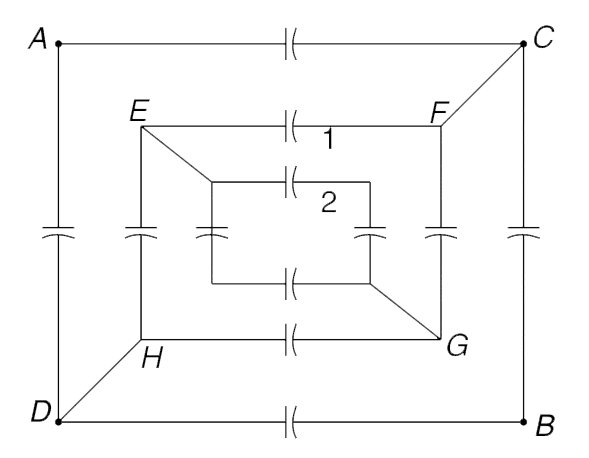
In the circuit shown in the figure all the capacitors have capacitance C.
(a) Find the charge on capacitors marked as 1 and 2 when a battery of emf V is connected across points A and B.
(b) Find the equivalent capacitance across points C and D marked in the Figure.
(c) Find the equivalent capacitance across points E and G.
View SolutionThe minimum number of capacitors (each of capacitance 2 μ F ) required to get an effective capacitance of 9 μ F is?
View Solution
Knowledge Check
In the arrangement of the capacitor shown in the figure, each C1 capacitor has capacitance of 3μF and each C2 capacitor has capacitance of 2μF then,
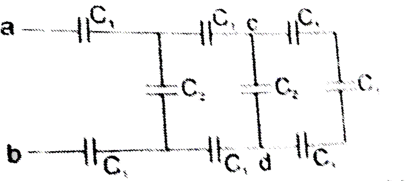
(ii) If Vab=900V, the charge on each capacitor nearest to the points 'a' and 'b' is :A300μCB600μCC450μCD900μCIn the arrangement of the capacitor shown in the figure, each C1 capacitor has capacitance of 3μF and each C2 capacitor has capacitance of 2μF then,
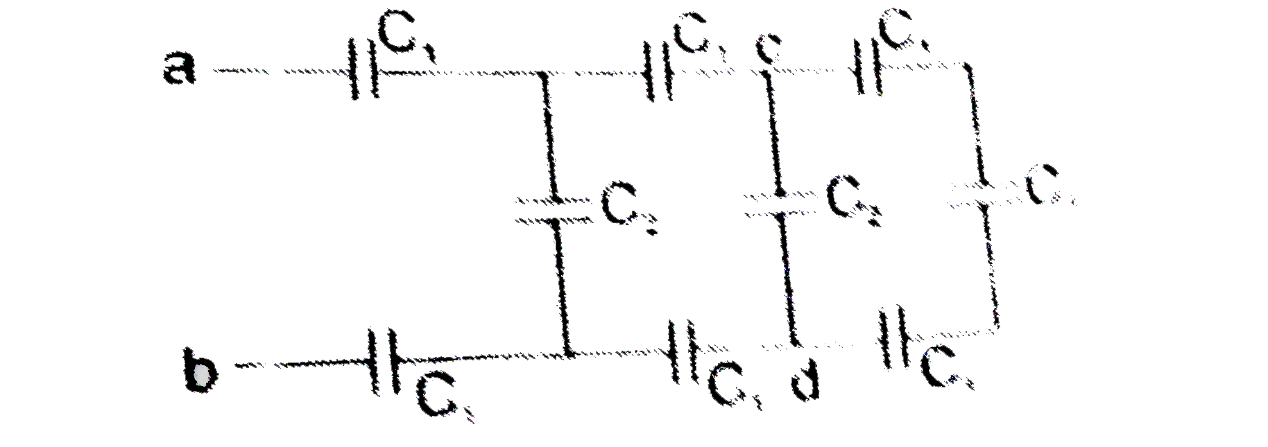
(i) Equivalent capacitance of the network between the points a and b is :A1μFB2μFC4μFD32μFFind the capacitance between P and O. Each capacitor has capacitance C.
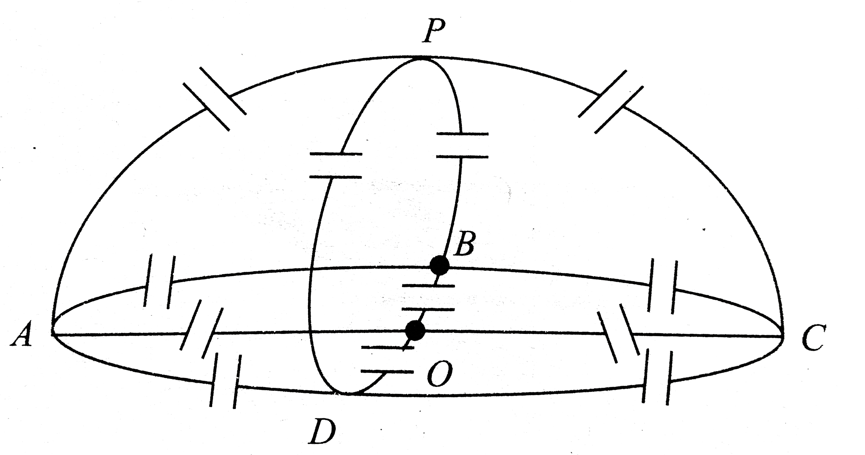 .A2CB3CC8CD6C
In the given circuit (as shown in figure), each capacitor has a capacity of 3μF. What will be the net charge on each capacitor ?
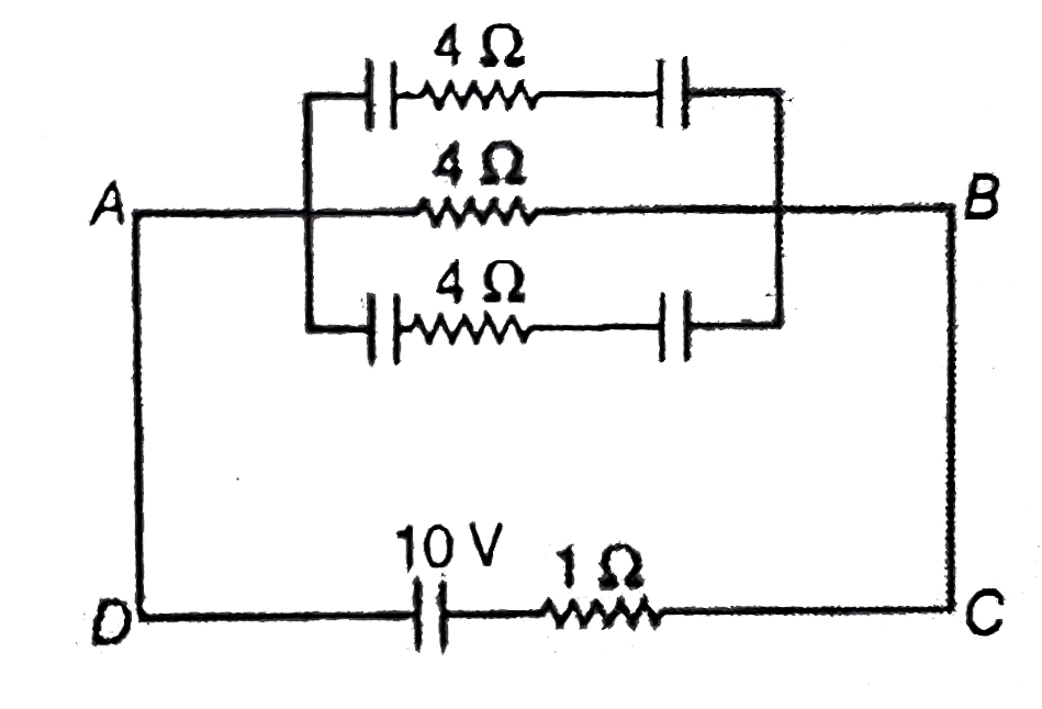
View SolutionA combination arrangement of the capacitors is shown in the figure
(i) C1=3μF,C2=6μF and C3=2μF then equivalent capacitance between 'a' and 'b' is :
View SolutionIn the circuit shown in the figure four capacitors are connected to a battery. The p.d across the 7μF capacitor is 6V.
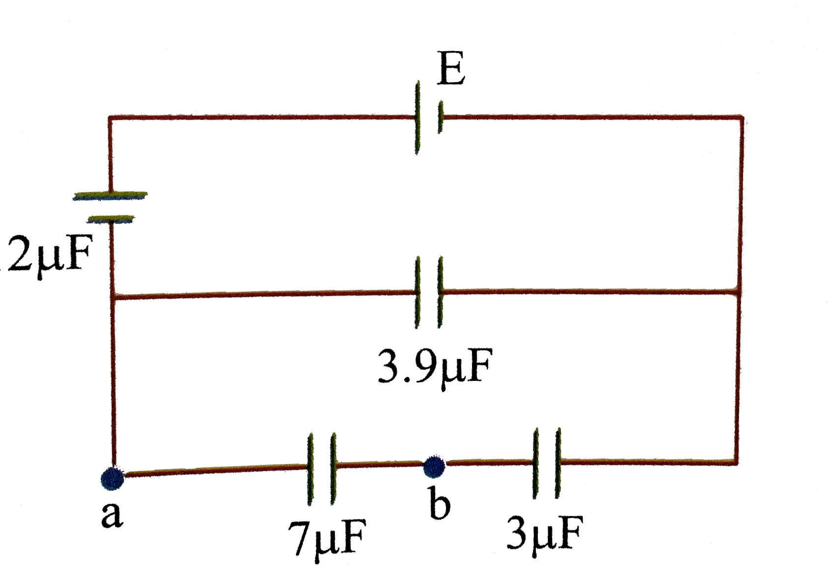 .
.
View SolutionIn the given arrangement of the capacitors, one 3μF capacitor has got 600μJ of energy. Then the potential difference across 2μF capacitor is

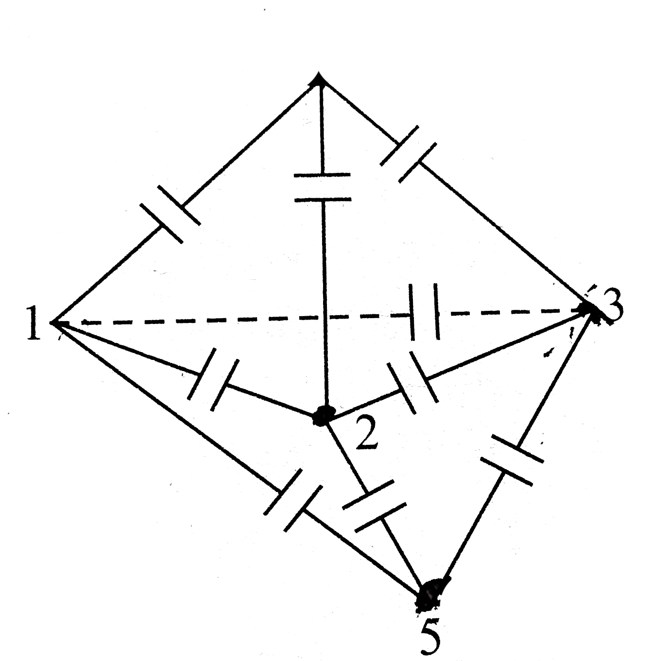
View SolutionEach capacitor has capacitance C.
 .
.
The capacitance between 1 and 3 is.
View Solution

