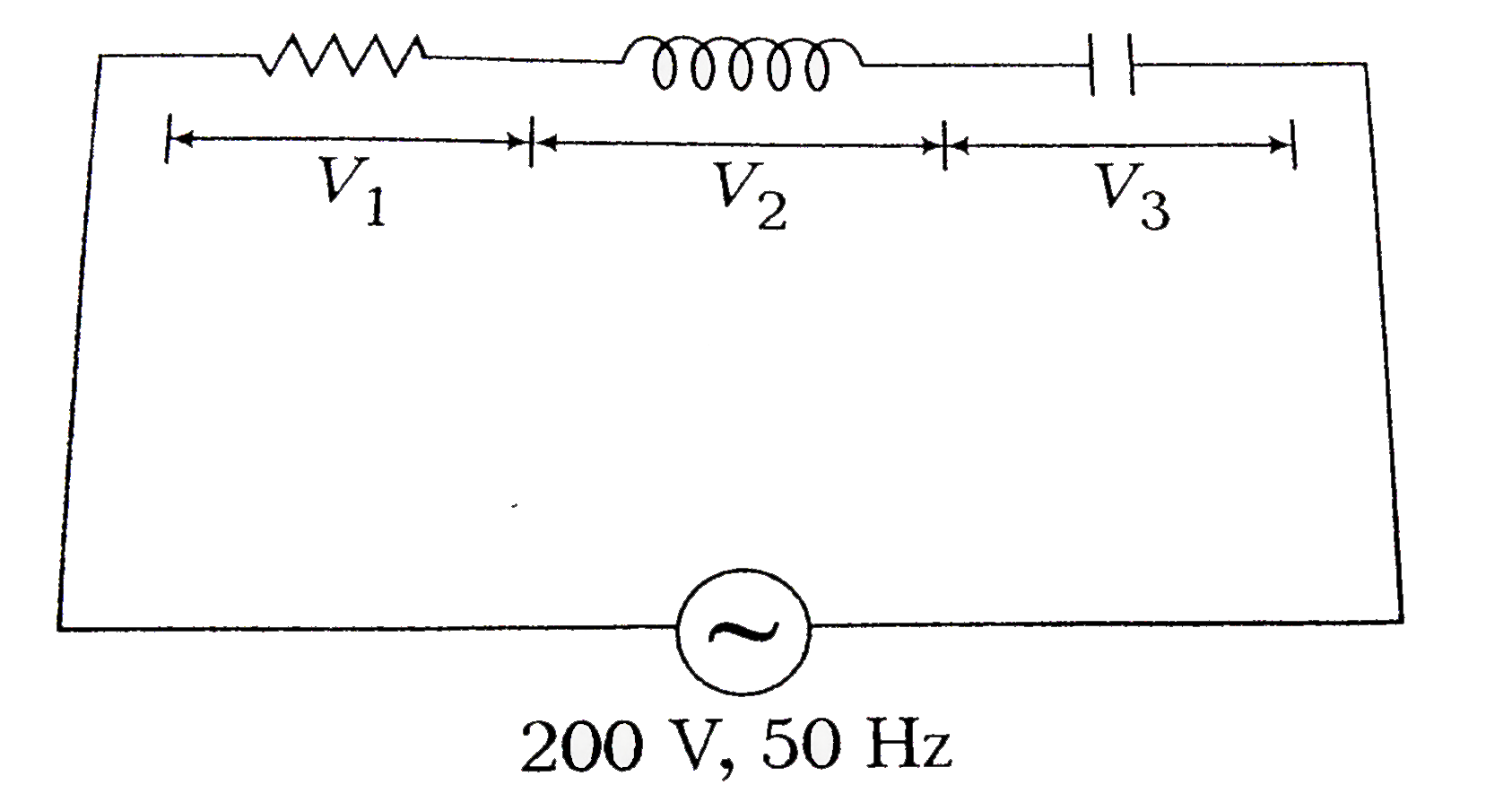
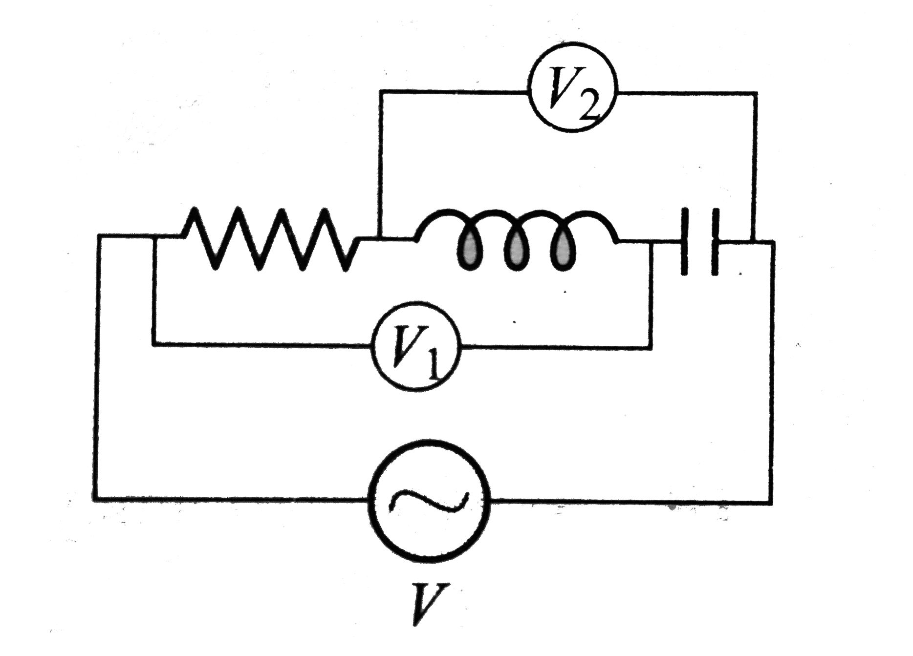
For series L-C-R circuit shown in the figure, the readings of and are same and each equal to 100 V .Then
A
the reading is 200 V
B
the reading of is 0
C
the circuit is in resonant mode and resonant frequency is 50 Hz
D
the inductive and capacitive reactance are equal
Video Solution
Text Solution
The correct Answer is:A, C, D
In resonance = and V =
|
Similar Questions
Knowledge Check
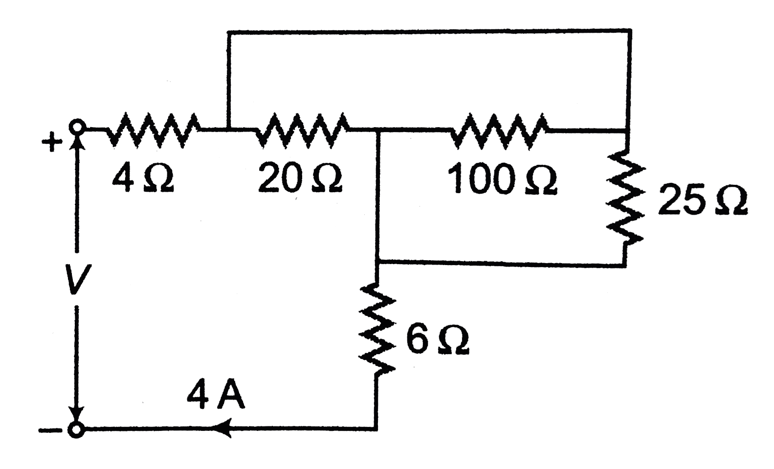
In the circuit shown in figure , V must be
 A50VB80VC100VD1290V
In the circuit shown in the figure, the ratio of VB as VC is
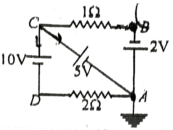 A−2/5B−5/2C1D1/3
In the circuit shown in figure value of VR is
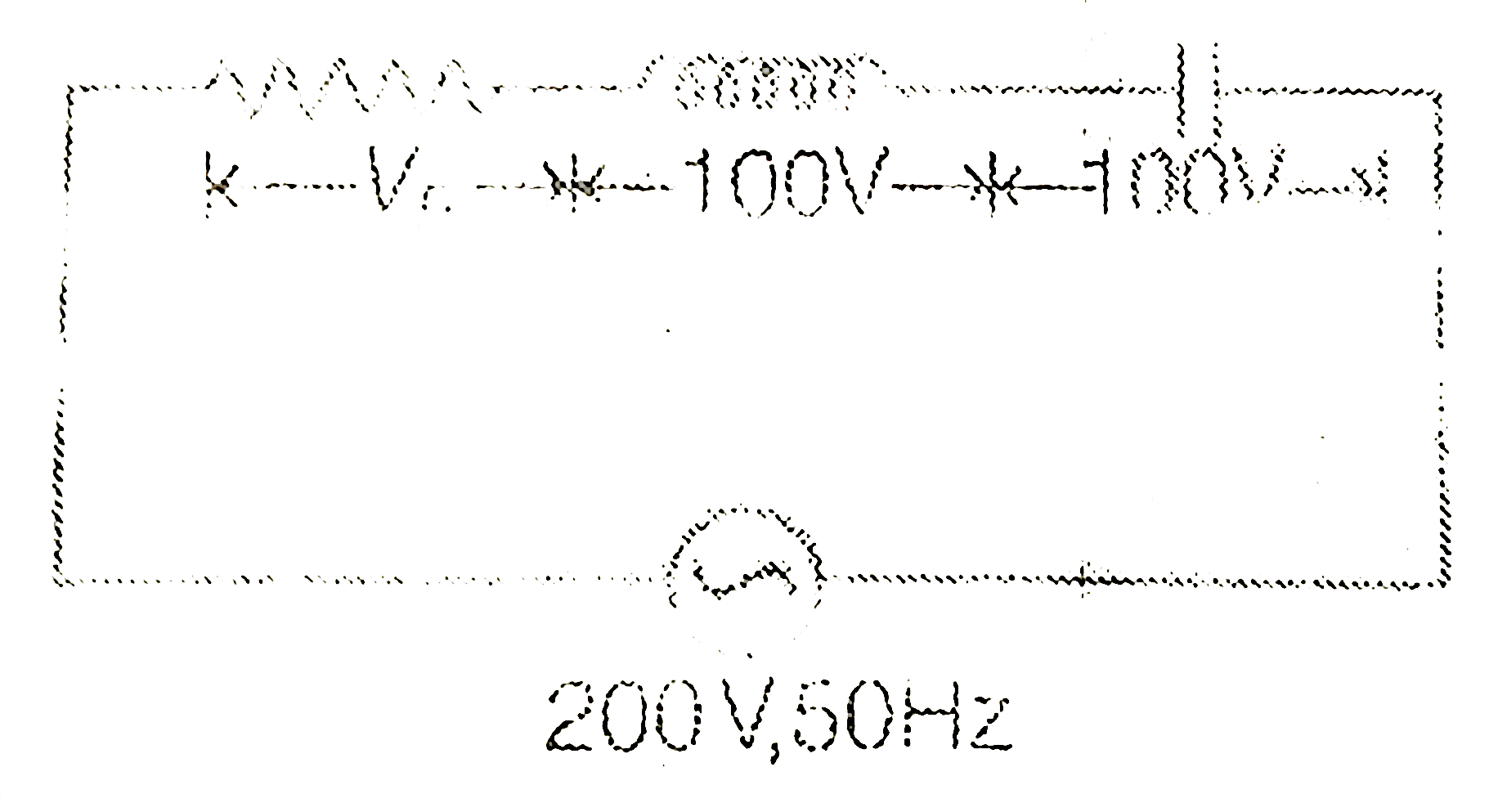 A400VB200VC300VDzero
In the series LCR circuit as shown in the figure, the voltmeter V and ammeter A reading are
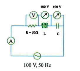
View SolutionIn the series LCR circuit as shown in the figure, the voltmeter V and ammeter A reading are

View SolutionIn the circuit shown, the readings of voltmeters V1,V2andV3 are given by
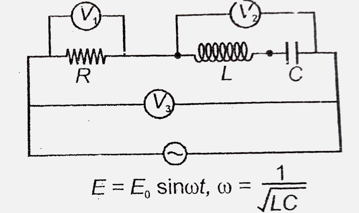
View SolutionIn a series CR circuit shown in figure,the applied voltage is 10V and the voltage across capacitor is found to be 8V
View SolutionIn an RLC series circuit shown in fig. the reading of voltmeters (V1)and(V2) are 100 V and 200 V respectively. The source voltage is 130 V. for this situation, mark out the correct statements (s).
View Solution

