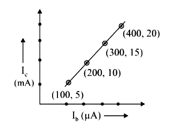
The transfer characteristic curve of a transistor, having input and output resistance respectively, is shown in the figure. The Voltage and Power gain, are respectively:

The correct Answer is:A
Step by step video, text & image solution for The transfer characteristic curve of a transistor, having input and output resistance 100Omega and 100kOmega respectively, is shown in the figure. The Voltage and Power gain, are respectively: by Physics experts to help you in doubts & scoring excellent marks in Class 12 exams.
Updated on:21/07/2023Topper's Solved these Questions
Similar Questions
In a common base transistor the value of load resistance in output and input circuit is 500 kω and 300 ω respectively calculate the voltage gain and power gain if value of current gain is 0.90
View SolutionCurrent gain of a transistor is 50 if the collector resistance is 5 k ω and input resistance is 1 k ω calculate the voltage gain
View Solution
Knowledge Check
If β,RLandr are the ac current gain, load resistance and the input resistance of a transistor respectively in CE configuration, the voltage and the power gains respectively are
AβRLrandβ2RLrBβrRLandβ2rRLCβRLrandβ(RLr)2DβrRLandβ(rRL)2If β,RLandr are the ac current gain, load resistance and the input resistance of a transistor respectively in CE configuration, the voltage and the power gains respectively are
AβRLrandβ2RLrBβrRLandβ2rRLCβRLrandβ(RLr)2DβrRLandβ(rRL)2If β,RL and r are the AC current gain, load resistance and the input resistance of a transistor respectively in CE configuration, the voltage and the power gains respectively are
AβRLrandβ2RLrBβrRLandβ2rRLCβRLrandβ(RLr)2DβrRLandβ(rRL)2
The output resistance of an n-p-n transistor is 4 kω and input resistance is 1kω if the current gain is 50 and output voltage is 4V then find the input voltage
View SolutionIn a transistor, current gain is 100 . If the load resistance is 3 and the input resistance is 1kohm, then what will be voltage gain?
View SolutionIn common emitter transistor, the input resistance is 200Ω and bad resistance is 40kΩ. If current gain is 80 then voltage gain is
View SolutionFor a common emitter amplifier, the voltage gain is 40. Its input and output impedances are 100 Ω and 400 Ω respectively. The power gain of the C.E. amplifier will be
View SolutionGraph between output current (Ic) and input current (IB) for common emitter of n−p−n transistor is given in the figure. If input resistance is 100Ω and output resistance is 100Kω. Find out voltage gain and power gain are
_2019_CBT7_E01_019_Q01.png)
View Solution
