Predict the polarity of the capacitor in the situation described in the figure below.
To predict the polarity of the capacitor in the given situation, we can follow these steps:
1. Identify the Components:
- We have a closed loop containing a capacitor with two plates labeled A and B.
- A bar magnet is moving towards the loop, and we need to analyze the effect of this motion on the capacitor.
2. Understand the Magnetic Field:
- The bar magnet has a north pole and a south pole. When the south pole of the magnet approaches the loop, the magnetic field lines are directed towards the south pole.
3. Determine the Change in Magnetic Flux:
- As the south pole moves closer to the loop, the magnetic flux through the loop increases. This is because more magnetic field lines are passing through the loop as the magnet approaches.
4. Apply Faraday's Law of Electromagnetic Induction:
- According to Faraday’s law, a change in magnetic flux induces an electromotive force (emf) in the loop. The induced emf (ε) can be expressed as:
ε=−dΦdt
- The negative sign indicates the direction of the induced emf according to Lenz's Law.
5. Determine the Direction of Induced Current:
- Since the magnetic flux is increasing, the induced current will flow in a direction that opposes this increase. This means the induced current will flow in a direction that creates a magnetic field opposing the incoming magnetic field.
6. Use the Right-Hand Rule:
- To find the direction of the induced current, we can use the right-hand rule. Curl the fingers of your right hand in the direction of the induced current; your thumb will point in the direction of the induced magnetic field.
- Since we want to oppose the increasing magnetic field (coming from the south pole), the induced current must flow in an anti-clockwise direction when viewed from the perspective of the approaching magnet.
7. Determine the Polarity of the Capacitor:
- If the induced current flows in an anti-clockwise direction, it means that the current enters plate A and exits plate B.
- Therefore, plate A will be positively charged (since current flows into it) and plate B will be negatively charged (since current flows out of it).
Conclusion:
- Plate A: Positive
- Plate B: Negative
- We have a closed loop containing a capacitor with two plates labeled A and B.
- A bar magnet is moving towards the loop, and we need to analyze the effect of this motion on the capacitor.
- The bar magnet has a north pole and a south pole. When the south pole of the magnet approaches the loop, the magnetic field lines are directed towards the south pole.
- As the south pole moves closer to the loop, the magnetic flux through the loop increases. This is because more magnetic field lines are passing through the loop as the magnet approaches.
- According to Faraday’s law, a change in magnetic flux induces an electromotive force (emf) in the loop. The induced emf (ε) can be expressed as:
ε=−dΦdt
- The negative sign indicates the direction of the induced emf according to Lenz's Law.
- Since the magnetic flux is increasing, the induced current will flow in a direction that opposes this increase. This means the induced current will flow in a direction that creates a magnetic field opposing the incoming magnetic field.
- To find the direction of the induced current, we can use the right-hand rule. Curl the fingers of your right hand in the direction of the induced current; your thumb will point in the direction of the induced magnetic field.
- Since we want to oppose the increasing magnetic field (coming from the south pole), the induced current must flow in an anti-clockwise direction when viewed from the perspective of the approaching magnet.
- If the induced current flows in an anti-clockwise direction, it means that the current enters plate A and exits plate B.
- Therefore, plate A will be positively charged (since current flows into it) and plate B will be negatively charged (since current flows out of it).
- Plate A: Positive
- Plate B: Negative
Topper's Solved these Questions
- UNIT–III & UNIT–IV MAGNETIC EFFECTS OF CURRENT AND MAGNETISM & E.M.I. AND ALTERNATING CURRENTBook:CBSE COMPLEMENTARY MATERIALChapter:UNIT–III & UNIT–IV MAGNETIC EFFECTS OF CURRENT AND MAGNETISM & E.M.I. AND ALTERNATING CURRENTExercise:SHORT ANSWER QUESTIONS (2 Marks)
Explore 41 Videos
- UNIT–III & UNIT–IV MAGNETIC EFFECTS OF CURRENT AND MAGNETISM & E.M.I. AND ALTERNATING CURRENTBook:CBSE COMPLEMENTARY MATERIALChapter:UNIT–III & UNIT–IV MAGNETIC EFFECTS OF CURRENT AND MAGNETISM & E.M.I. AND ALTERNATING CURRENTExercise:SHORT ANSWERS QUESTIONS (3 Marks)
Explore 27 Videos
- SAMPLE QUESTION PAPER 2019Book:CBSE COMPLEMENTARY MATERIALChapter:SAMPLE QUESTION PAPER 2019Exercise:Section C
Explore 19 Videos
Similar Questions
Predict the polarity of the capacitor in the situation described by adjoining Fig. 6.27. Explain the reason too.

View SolutionAnswer the following quesitons : (a) A closed conducting loop moves normal to the electric fieldd between the plates of a large capacitor. Is a current induced in the loop when it is (i) wholly inside the capacitor (ii) partially outside the plates of capacitor. Electric field is normal to the plane of the loop.
(b) A rectangular loop and a circular loop are moving out of a uniform magnetic field region to a field free region with a constant velocity, Fig. In which loop do you expact the induced e.m.f. to be constant during the passage out of the field region, the field is normal to the loops ?
(c ) Predict the polarity of the capacitor in the situation described by Fig.
View Solution
Knowledge Check
The reaction described below is :
 ASE2BSN1CSN0DSN2
The charge on the capacitor as in figure is
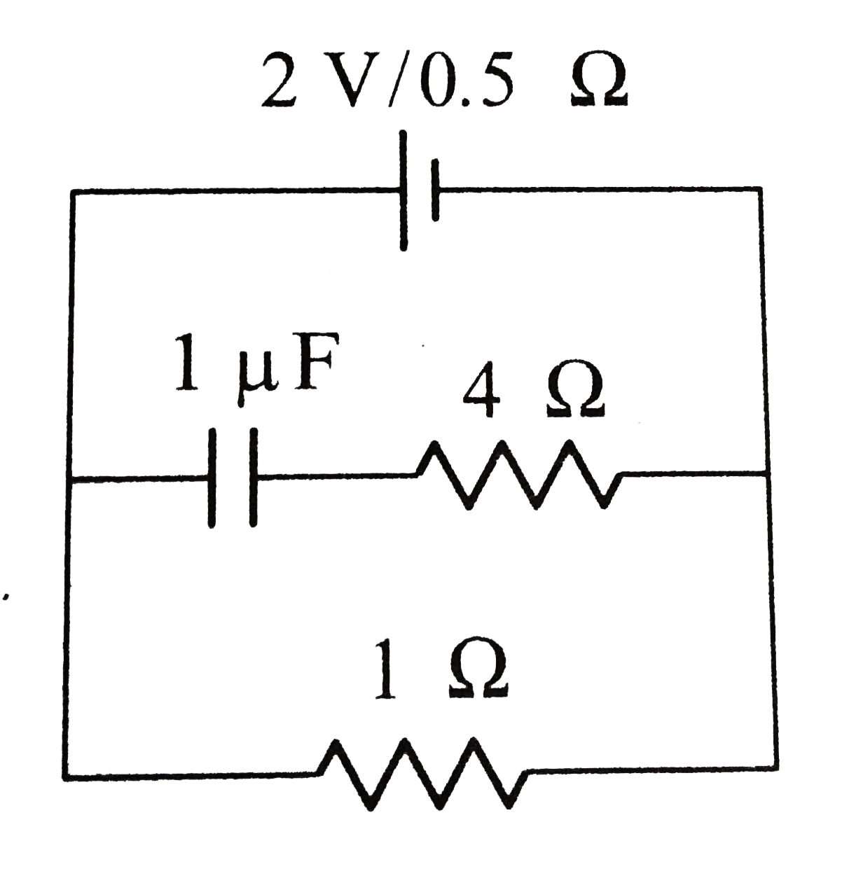 A2μCB23μCC43μCDzero
Find the size of the image formed in the situation shown in figure.
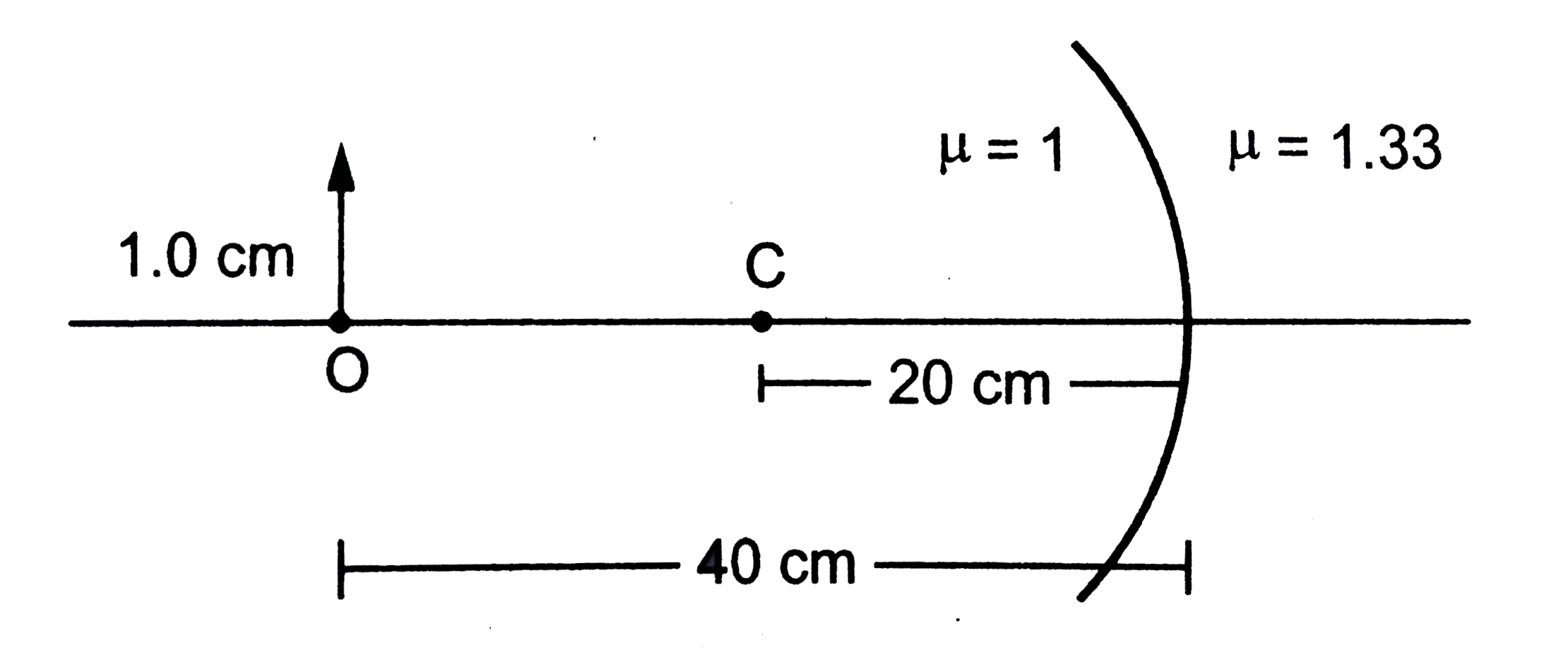 A−0.6cmB+0.6cmC+0.1cmD+1.2cm
Predict the polarity of the capacitor when the two magnets are quickly moved in the directions marked by arrows.

View SolutionPredict the direction of indcued current in the situation described by the following Fig.
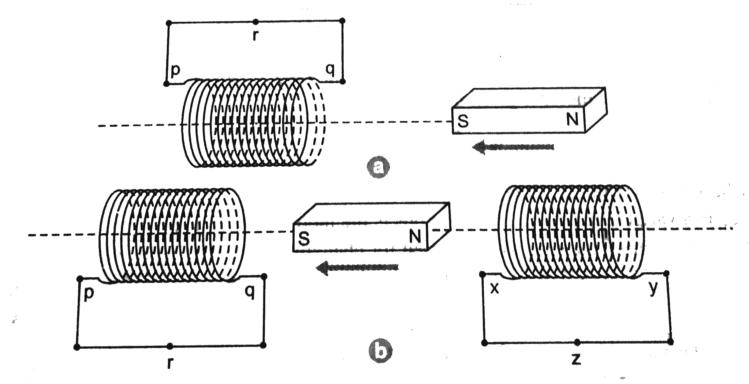
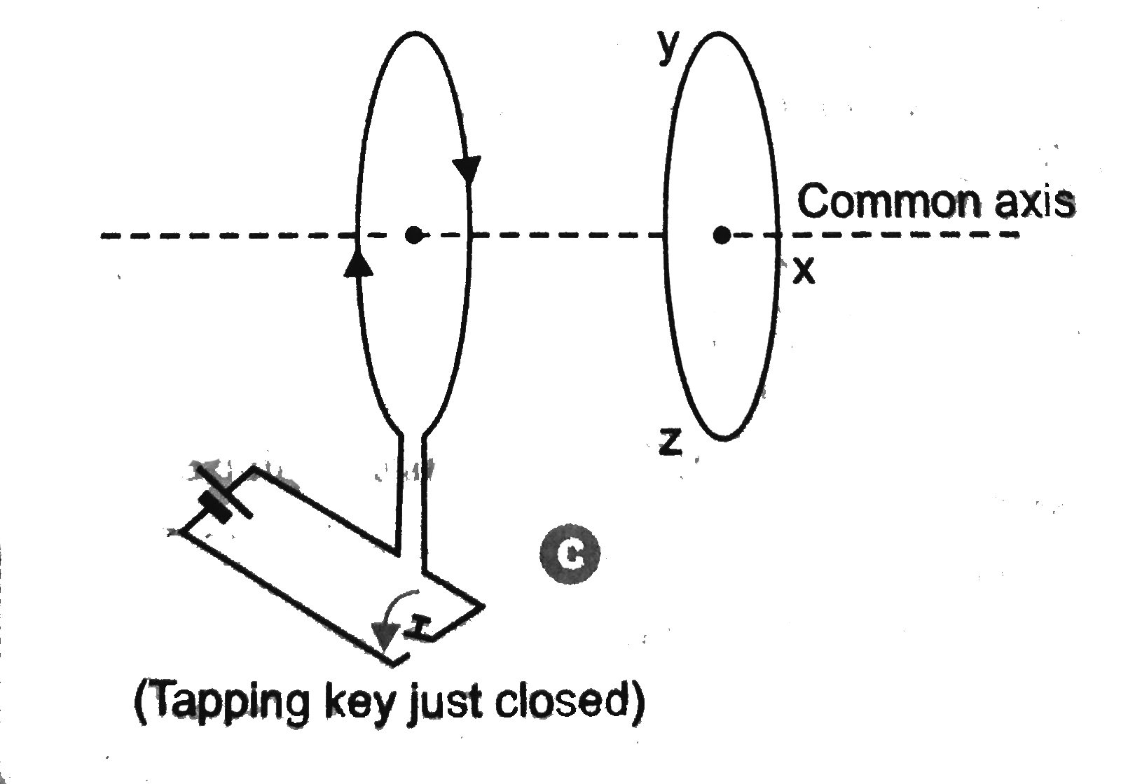
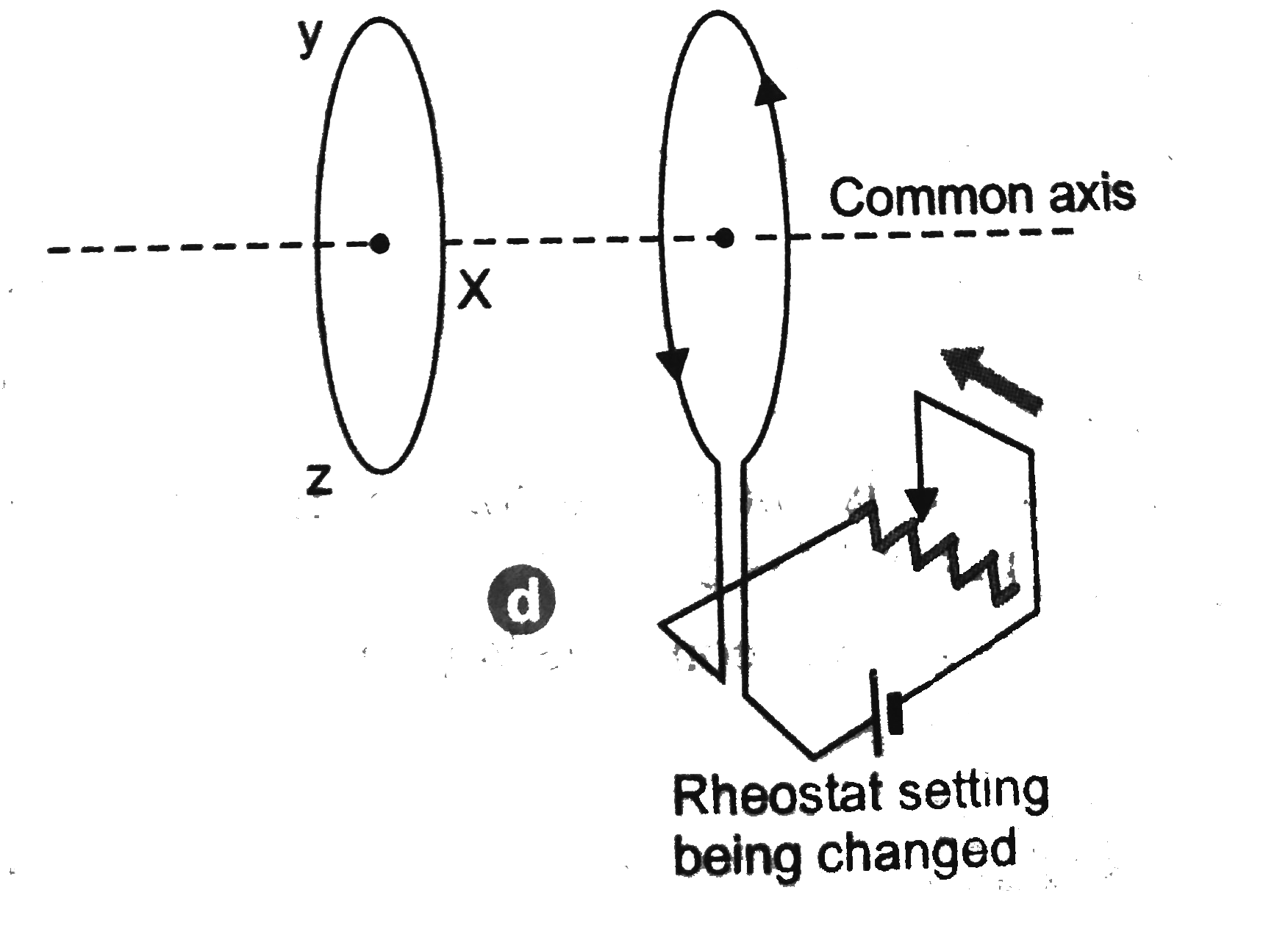
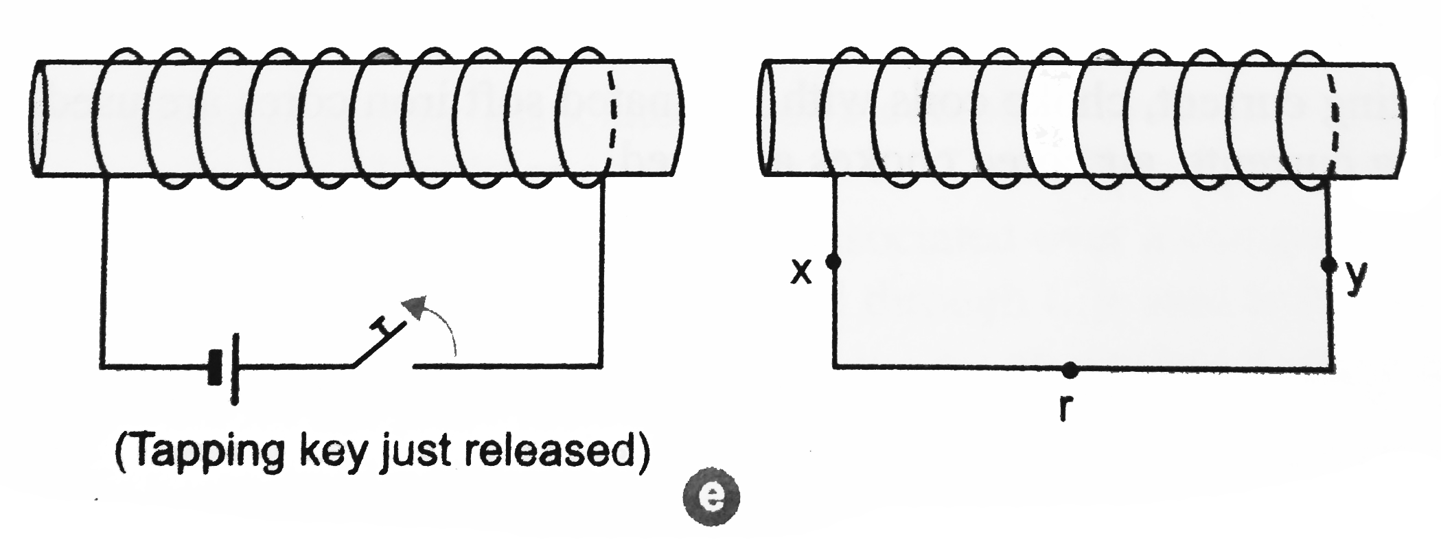
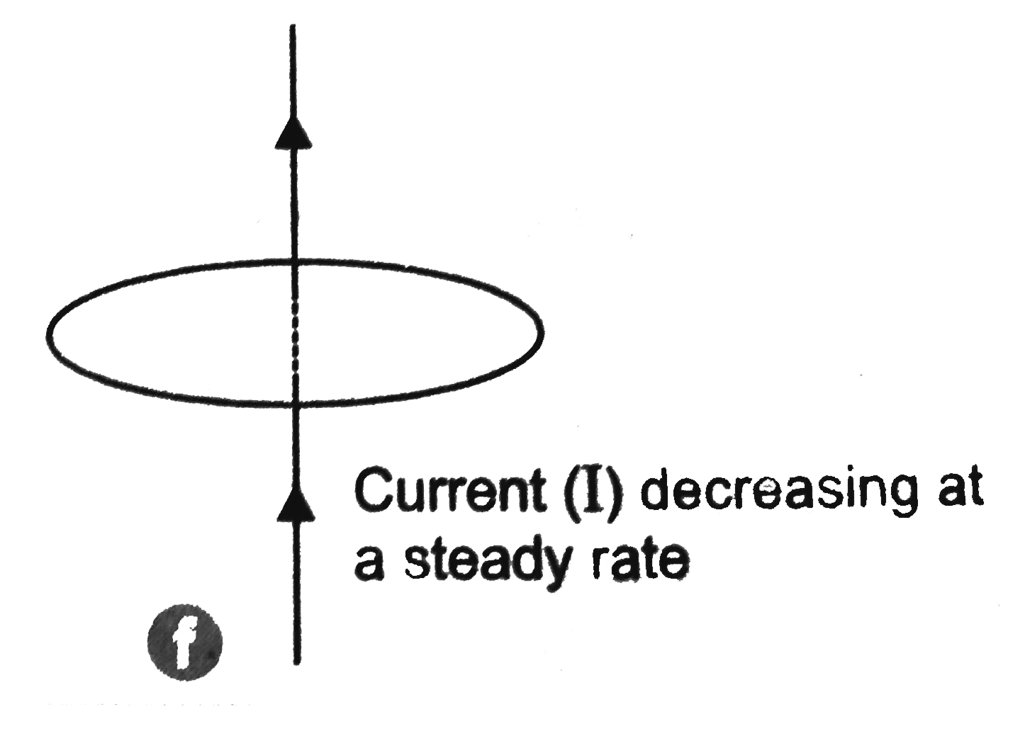
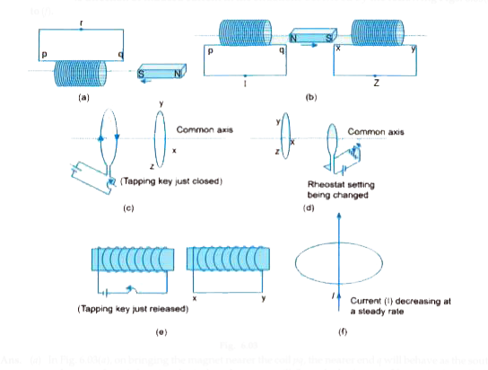
View SolutionPredict the direction of induced current in the situations described by the following Figs. 6.03(a) to (f).
View SolutionFind the acceleration of the A and B in the situation show in the figure
View SolutionWhich of the following features describes the figure given below?

View Solution

