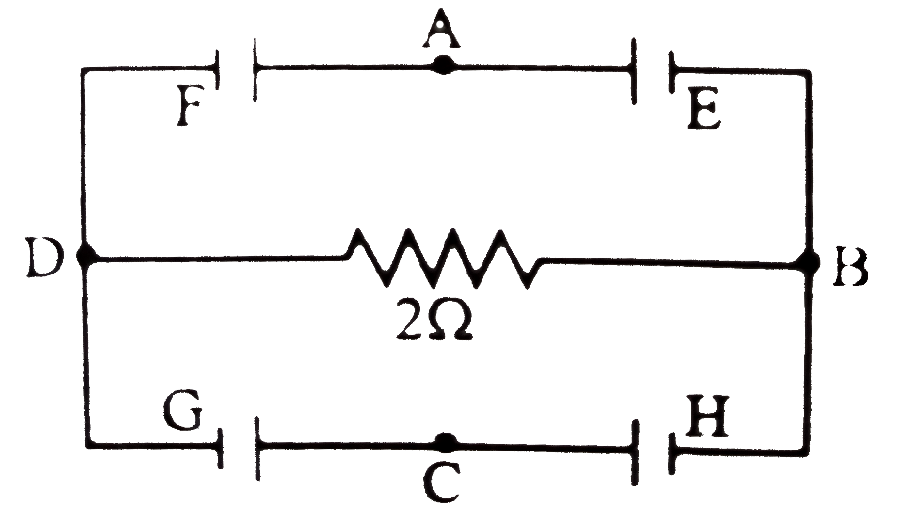
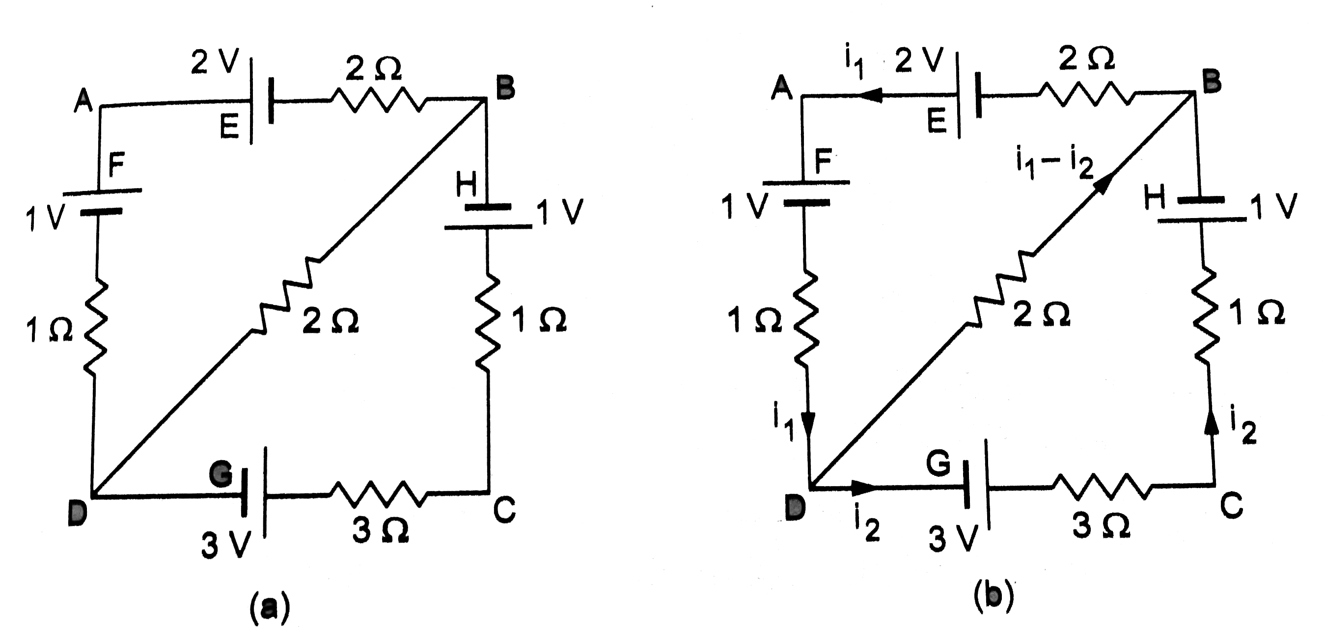
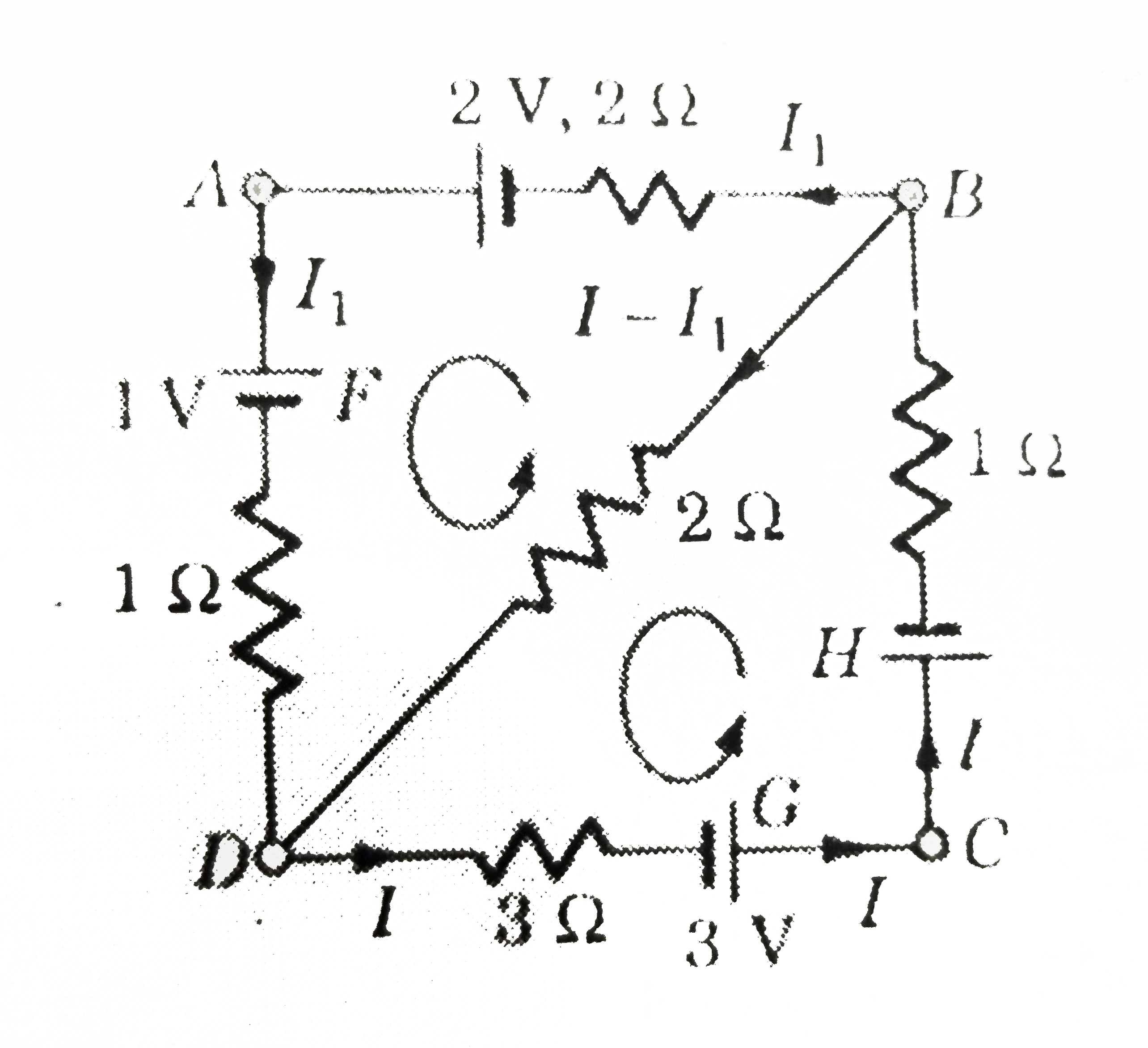
In the circuit shown E,F,G and H are cells of emf 2V,1V,3V and 1V respectively and their internal resistance are 2Ω,1Ω,3Ω and 1Ω respectively.
(i) 213V,(ii)VG=2113V,VH=913V
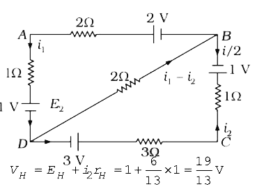
Applying kirchoff's second law in loop BADB, 2−2j1−j1−1−2(j1−j2)=0
Similarly applying kirchoff's second law in loop BDCB
2(j1−j2)+3−3j2−j2−1=0………(ii)
Solving Eqs. (i) and (ii) we get
j1=513,j2=613andj1−j2=−113
(i) Potential difference between B and D,
VB+2(j1−j2)=VD
∴VB−VD=−2(j1−j2)=213V
(ii) VG=EG−j2rG=3−613×3=2113V,VH=EH+j2rh=1+613×1=1913V
Similar Questions
In the circuit shown in figure-3.159 cells E,F,G and H are of EMF 2V, 1V,3V and 1V respevitly and their internal resitance are 2Ω,1Ω,3Ω and 1Ω respectively Calculate
(a) The potential difference between points B and D
(d) The potential difference across the terminals of the cell G and H.
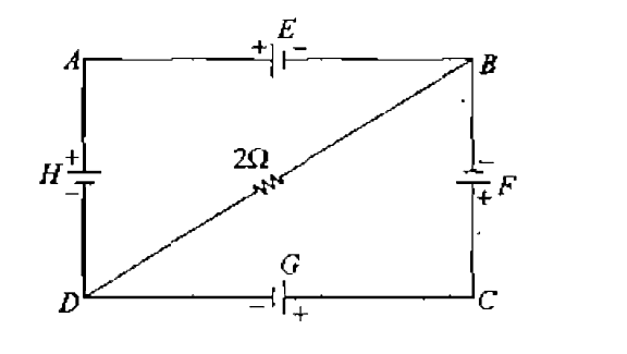
View SolutionIn the circuit shown in E, F, G, and H are cells of emf 2,1,3 and 1 V, respectively. The resistances 2Ω,1Ω,3Ωand1Ω are their respectivle internal resistances.
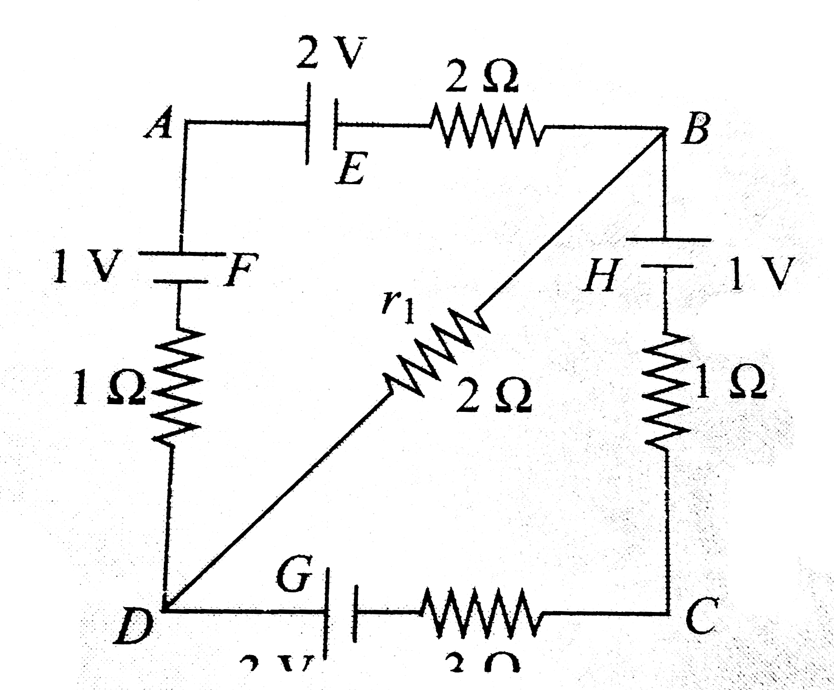
i. Find the potential difference between B and D.
(ii) Calculate the potential differences across the terminals of each of the cells G and H.
View Solution
Knowledge Check
In the circuit shown in figure E,F, G and H are cell of emf 2,1,3, and 1V respectively. The resistances 2,1,3 and 1(Omega)are their respective internal resistance .Calculate (a)the potential difference between B and D and (b) the potential differences across the terminals of each of each of the cells G and H.
 A2112V.B213V.C2114V.D2113V.
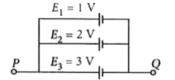
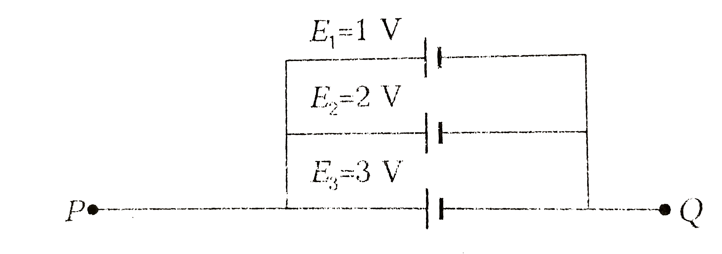
A circuit consists of three batteries of emf E1 = 1 V, E2=2VandE3=3V and internal resistances 1Ω,2Ωand1Ω respectively which are connected in parallel as shown in the figure. The potential difference between points P and Q is
 A1.0VB2.0VC2.2VD3.0V
In the circuit shown in fig. the cell has emf 10V and internal resistance 1Ω
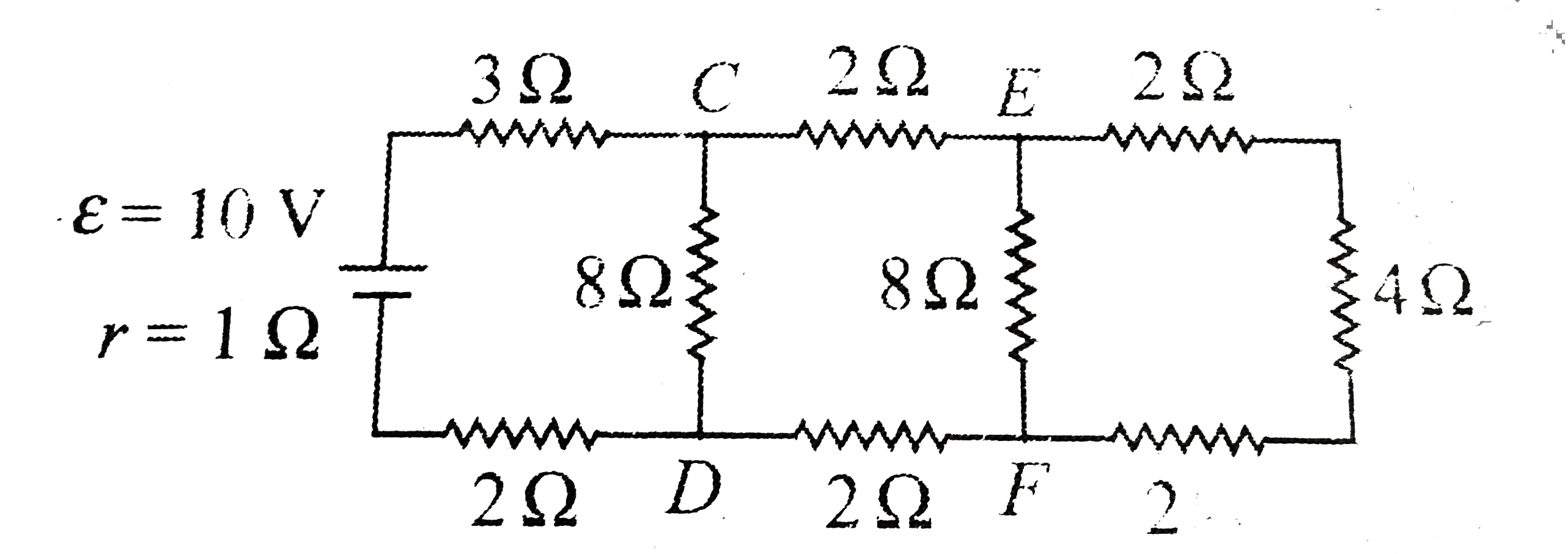 AThe current through the 3Ω resistor is 1A.BThe currents through the 3Ω resistor is 0.5 A.CThe currents through the 4Ω resistor is 0.5 ADThe current through the 4Ω resistor is 0.25 A.
Three cells are connected in parallel, with their like poles connected together, with wires of negligible resistance. If the emf of the cell are 2V, 1V and 4V and if their internal resistance are 4Ω,3Ωand2Ω respectively, find the current through each cell.
View Solution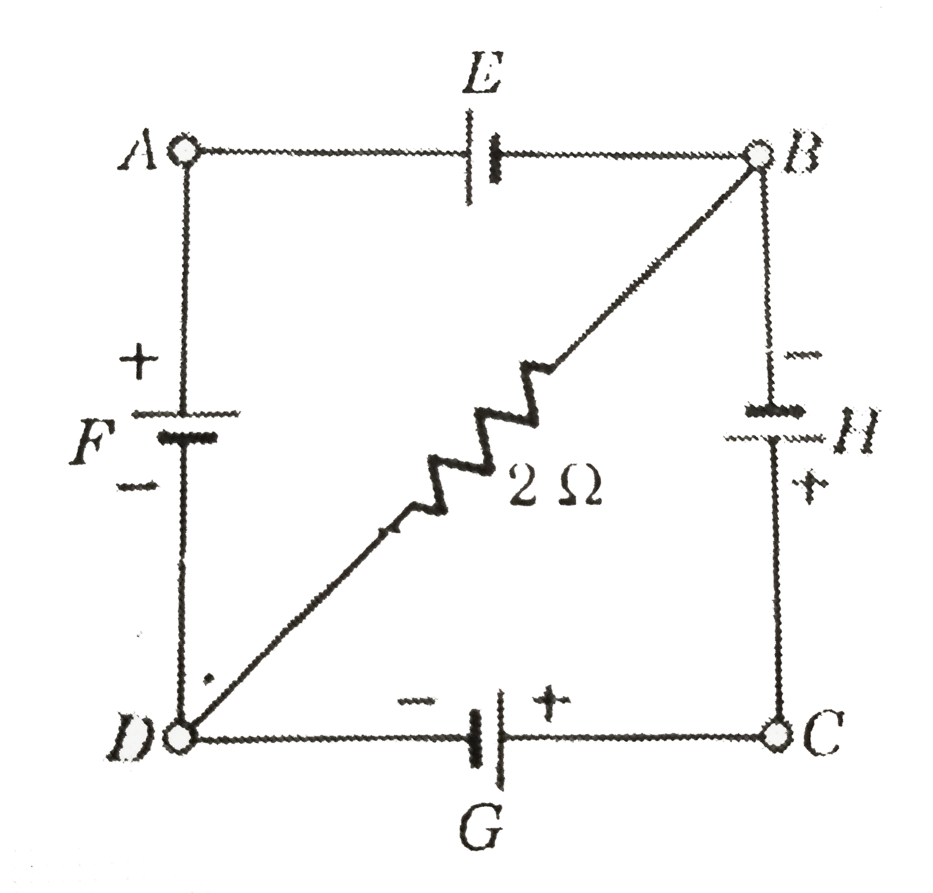
In the circuit shown in figure. The cells E,F,G and H have e.m.f's 2,1,3 and 1 V and internal resistance 2,1,3 and 1Ω respectively. Find the potential differences between points B and D, and across the terminals of the cells G and H.
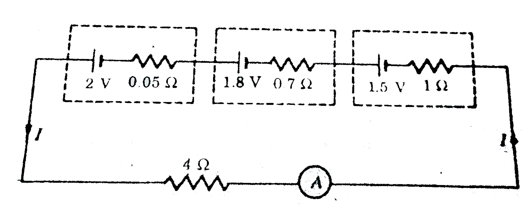
View SolutionThree cells of emf 2.0 v, 1.8 V and 1.5 V are connected in series. Their internal resistances are 0.05Ω,0.7Ω and 1Ω respectively. If the battery is connected to an external resistor of 4Ω via a very resistance ammeter, what would be the reading in the ammeter ?
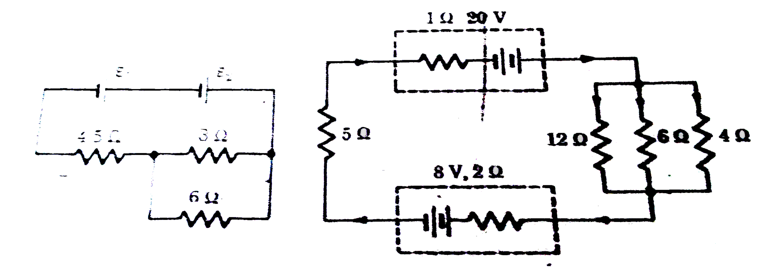
View SolutionIn the circuit shown in Fig. 4.68, the cells ε1 and ε2 have emf's of 4 V and 8 V and internal resistances of 0.5Ω and 1Ω respectively. Calculate the current in each resistance.
View SolutionA circuit consists of three batteries of emf E1=1V,E2=2V and E3=3V and internal resistance 1Ω,2Ω and 1Ω respectively which are connected in parallel as shown in figure. The potential difference between points P and Q is
View Solution
