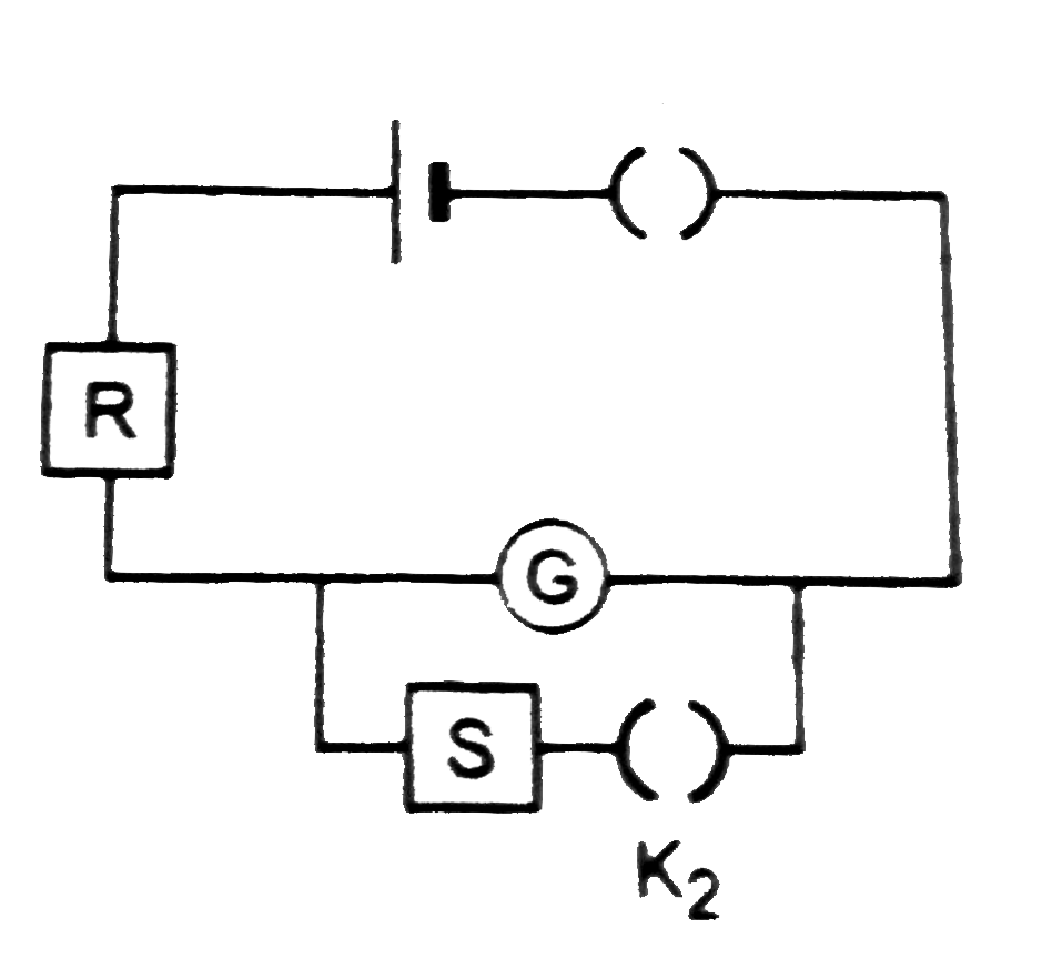
the galvameter deflection , when key K1 is clossed but K2 is open equals θ0 (see figure ) On clossing k2 also and adjusting R2 to 5Ω , the deflection in galvanometer becomes θ05 the resistnce of the galvanometer is then , given by [Neglect the internal resistance of battery]:
![the galvameter deflection , when key K(1) is clossed but K(2) is open equals theta(0) (see figure ) On clossing k(2) also and adjusting R(2) to 5Omega , the deflection in galvanometer becomes (theta(0))/(5) the resistnce of the galvanometer is then , given by [Neglect the internal resistance of battery]:](https://d10lpgp6xz60nq.cloudfront.net/physics_images/JMA_2019_PC_IEH_12_JAN_I_E01_027_Q01.png)
22Ω
25Ω
12Ω
5Ω
Deflection in galvanometer is proportional to galvanometer current
θ0∝ig⇒θ0K=ig
Situation 1 , Kθ0=V220+R………(i)
Situation Kθ05=V(220+5R5+R)×55+R
From (i) and (2) , R=22Ω
Similar Questions
Knowledge Check
In the circuit, shown in figure. R=5000Ω. If key K1 is closed, galvanometer shows a deflection of 30 scale division. On closing key K2 and making S=20Ω, the deflection of galvanometer reduces to 15 division. The resistance of galvanometer is
 A50ΩB30ΩC20ΩD15Ω
100 current gives a full scale deflection in a galvanometer of 2Ω resistance. The resistance connected with the galvanometer to convert it into a voltmeter to measure V 5 is
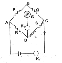
A98ΩB52ΩC50ΩD48ΩThe resistances P,Q,R and S in the bridge shown are adjusted such that the deflection in the galvanometer G is zero when both the keys K1 and K2 are inserted. The galvanometer will show a momentary deflection if
 Afirst K2 is inserted and then K1Bfirst K1 is inserted and then K2CK1 and K2 are both inserted but an additional resistance is put in the arm BDDin all the above cases
When a shunt of 4Ω is attahced to a galvanometer, the deflection reduces to 15th. If an additional shunt of 2Ω is attached. What will be the deflection?
View SolutionWhen a Laclanche cell is connected to a 10Ω resistance then a current of 0.25 ampere flows in the circuit. If the resistance is reduced to 4Ω then current becomes 0.5ampere. The internal resistance of galvanometer will be-
View SolutionIf resistance of voltmeter is 10000Ω and resistance of ammeter is 2Ω then find R when voltmeter reads 12 V and ammeter reads 0.1 A
View Solution
A two terminal when connected in series with a battery and a galvanometer in series with it through a two way key as shown in figure. The galvanometer shows maximum deflection which gradually decreases to zero, when key k1 is close and k2 open. Now key k1 is open and k2 is closed. Now battery is disconnected and galvanometer is directly connected to the same device the deflection in galvanometer is maximum and reversed and decreases to zero gradually. The device is-
View SolutionIn the given figure, when galvanometer shows no deflection, the current (in ampere) flowing through 5Ω resistance will be

View Solution
