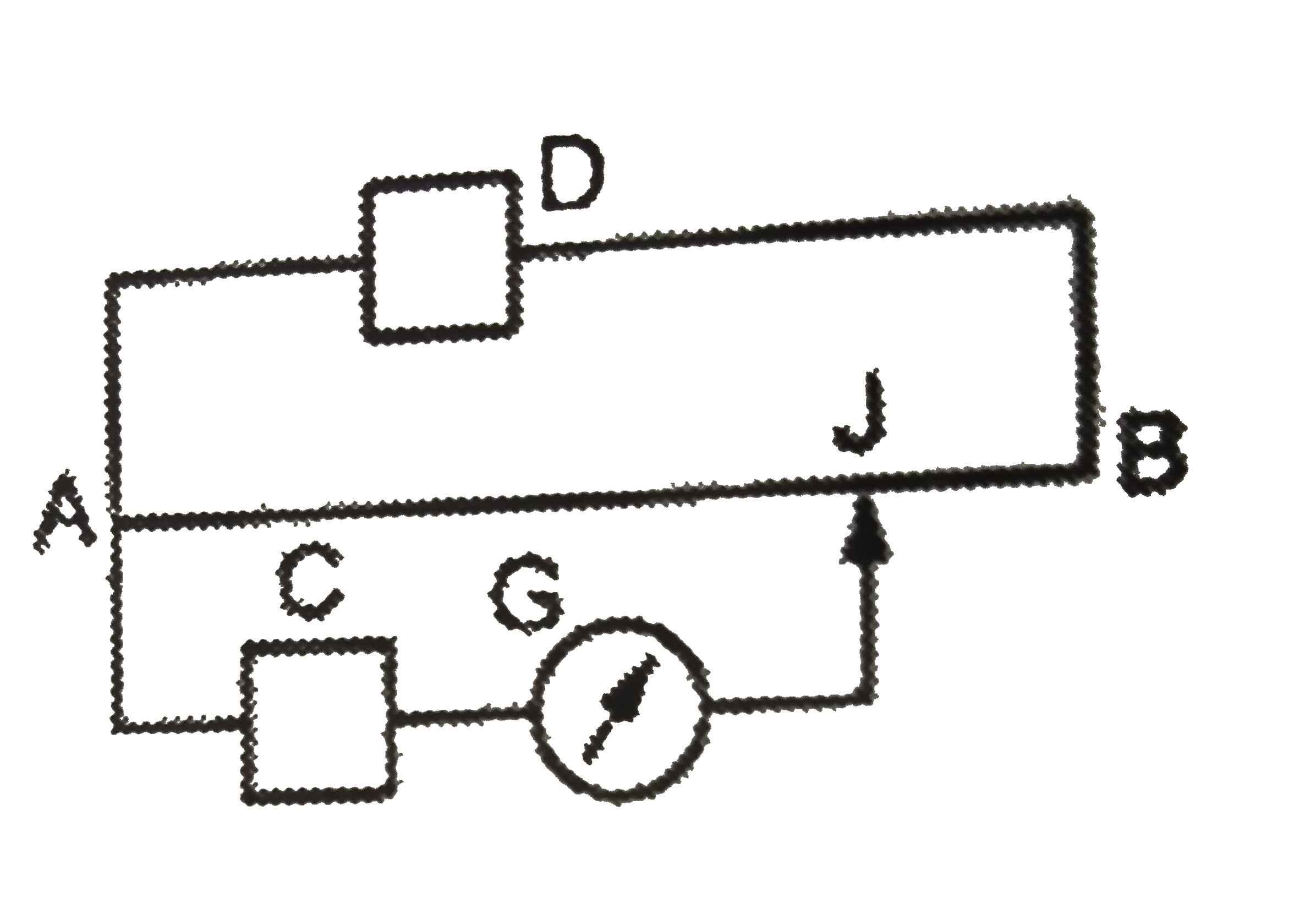
In apotentiometer arrangement E1 is the cell establishing current in primary circuit E2 is the cell to be measured . AB is the potentiometer wire and G is a galvanometer . Which of the following are the essential condition for balance to be obtained.
The emf of E1 must be greater than the emf of E2
Either the positive terminals of both E1andE2 or the negative terminals of both E1andE2 must be joined to one end of potentiometer wire.
The positive terminals of E1andE2 must be joined to one end of potentiometer wire.
The resistance of G must be less than the resistance of AB.
The correct Answer is:A,B
To determine the essential conditions for balance in a potentiometer arrangement, we need to analyze the setup and the requirements for achieving a balanced condition. Here’s the step-by-step solution:
Step 1: Understand the Potentiometer Setup
In a potentiometer setup, we have:
- E1: The cell that establishes the current in the primary circuit.
- E2: The cell whose voltage we want to measure.
- AB: The potentiometer wire where the voltage drop occurs.
- G: The galvanometer used to detect the balance point.
Step 2: Condition for Balance
For balance to be obtained in the potentiometer:
- The voltage across the potentiometer wire (V_AB) must be equal to the voltage of the cell being measured (E2). This means that the potential difference across the length of the wire must match the voltage of the cell.
Step 3: Voltage Relationship
The relationship can be expressed as:
- \( V_{AB} \geq E2 \)
This means that the voltage across the potentiometer wire must be greater than or equal to the voltage of the cell being measured.
Step 4: Current in the Circuit
The current established by the primary cell (E1) must be sufficient to create a voltage drop across the potentiometer wire that can equal or exceed E2. Therefore:
- The electromotive force (emf) of E1 should be greater than E2 for the potentiometer to function correctly.
Step 5: Connection of Terminals
The terminals of the cells must be connected properly:
- The positive terminal of E1 and E2 must be connected to one end of the potentiometer wire (or the negative terminals can be connected to the same end). This ensures that the potentials are referenced correctly.
Step 6: Resistance Considerations
The resistance of the galvanometer (G) should be less than the resistance of the potentiometer wire (AB):
- This is to ensure that when the galvanometer is connected, it does not draw significant current that would affect the balance condition.
Conclusion
The essential conditions for balance in a potentiometer arrangement are:
1. \( V_{AB} \geq E2 \)
2. The emf of E1 should be greater than E2.
3. The terminals of E1 and E2 must be connected correctly.
4. The resistance of the galvanometer must be less than the resistance of the potentiometer wire.
In a potentiometer setup, we have:
- E1: The cell that establishes the current in the primary circuit.
- E2: The cell whose voltage we want to measure.
- AB: The potentiometer wire where the voltage drop occurs.
- G: The galvanometer used to detect the balance point.
For balance to be obtained in the potentiometer:
- The voltage across the potentiometer wire (V_AB) must be equal to the voltage of the cell being measured (E2). This means that the potential difference across the length of the wire must match the voltage of the cell.
The relationship can be expressed as:
- \( V_{AB} \geq E2 \)
This means that the voltage across the potentiometer wire must be greater than or equal to the voltage of the cell being measured.
The current established by the primary cell (E1) must be sufficient to create a voltage drop across the potentiometer wire that can equal or exceed E2. Therefore:
- The electromotive force (emf) of E1 should be greater than E2 for the potentiometer to function correctly.
The terminals of the cells must be connected properly:
- The positive terminal of E1 and E2 must be connected to one end of the potentiometer wire (or the negative terminals can be connected to the same end). This ensures that the potentials are referenced correctly.
The resistance of the galvanometer (G) should be less than the resistance of the potentiometer wire (AB):
- This is to ensure that when the galvanometer is connected, it does not draw significant current that would affect the balance condition.
The essential conditions for balance in a potentiometer arrangement are:
1. \( V_{AB} \geq E2 \)
2. The emf of E1 should be greater than E2.
3. The terminals of E1 and E2 must be connected correctly.
4. The resistance of the galvanometer must be less than the resistance of the potentiometer wire.
Topper's Solved these Questions
- CURRENT ELECTRICITYBook:MOTIONChapter:CURRENT ELECTRICITYExercise:EXERCISE -3 (Level -I) SECTION A- Definition of Current , Current Density , Drift Velocity
Explore 2 Videos
- CURRENT ELECTRICITYBook:MOTIONChapter:CURRENT ELECTRICITYExercise:EXERCISE -3 (Level -I) SECTION B- Resistance & resistivity ,Ohms law +VI (Volt -Curr.) Characteristics +Colour Code + Temp . Dependence
Explore 8 Videos
- CURRENT ELECTRICITYBook:MOTIONChapter:CURRENT ELECTRICITYExercise:EXERCISE -2 (Level -II) SECTION E- Electrical Power & Energy
Explore 3 Videos
- CONSTRAINED MOTION Book:MOTIONChapter:CONSTRAINED MOTION Exercise:EXAMPLES
Explore 12 Videos
- ELASTICITYBook:MOTIONChapter:ELASTICITYExercise:EXERCISE -3
Explore 60 Videos
Similar Questions
In a potentiometer experiment it is found that no current passes through the galvanometer when the terminals of the cell are connected across 0.52m of the potentiometer wire. If the cell is shunted by a resistance of 5Ω balance is obtained when the cell connected across0.4m of the wire. Find the internal resistance of the cell.
View SolutionThe balancing length for a cell in a potentiometer experiment is 45 cm. In the balanced condition, the current through the potentiometer wire is 2 A. If the total length of the potentiometer wire is 1 m and its total resistance is60Ω , the emf of the cell is (in Volts) _________.
View Solution
Knowledge Check

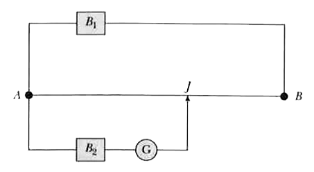
The figure shows a potentiometer arrangement. D is the driving cell. C is the cell whose emf is to be determined. AB is the potentiometer wire and G is a galvanometer. J is a sliding contact which can touch any point on AB. Which of the following are essential conditions for obtaining balance?AThe emf of D must be greater than the emf of CBEither the positive terminals of both D and C or the negative terminals of both D and C must be joined to A.CThe positive terminals of D and C must be joined to ADThe resitance of G must be less than te resistance of ABThe below figure shows a potentiometer arrangement, where B1 is the driving cell, B2 is the cell whose emf is to be determined. AB is the potentiometer wire and G is the galvanometer. J is a sliding contact which can touch any point on AB. Which of the following are essential conditions for obtaining balance?
 AThe emf of B1 must be greater than the emf of B2BEither the positive terminals of both B1andB2 or the negative terminals of both B1andB2 must be joined at ACThe positive terminals of B1andB2 must be joined to ADThe resistance of G must be less than the resistance of AB
In a potentiometer arrangement, a cell of emf 1.5 V gives a balance point at 27 cm length of wire. If the cell is replaced by another cell and balance point shifts to 54 cm, the emf of the second cell is :
A3VB1.5VC0.75VD2.25V
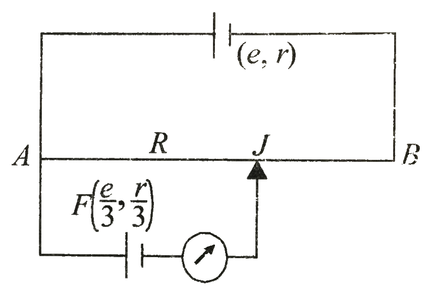
A potentiometer arrangement is shows in Fig. 6.62. The driver cell has emf e and internal resistance r. The resistance of potentiometer wire AB is R.F is the cell of emf e/3 and internal resistance r/3. Balance point (J) can be obtained for all finite value of

View SolutionThe potentiometer wire of resistance R is connected in series with a cell of e.m.f. E and of resistance Rh. The current flowing through the potentiometer wire is
View SolutionIn a potentiometer arrangement , a cell of EMF 2 V gives a balance point at 40 cm length of the wire . If this cell is replaced by another cell and the balance point shifts to 60 cm , then the EMF of the second cell is
View SolutionFor a potentiometer to function, the emf of the cell (E) in the primary circuit compared to the emf of the cell (E1) in the secondary circuit should have a realtion
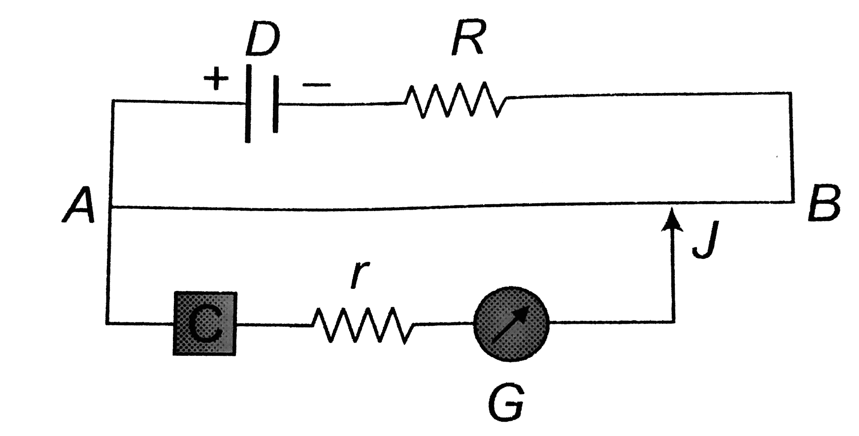
View SolutionIn the given potentiometer circuit, the resistance of the potentiometer wire AB is R0.C is a cell of internal resistandce r. The galvanometer G does not give zero following cannot be a reason for this ?

View Solution