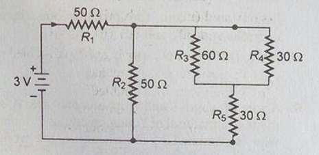
In the circuit shown , the resistances are given in ohms and the battery is assumed ideal with emf equal to 3.0 volts The resistor that dissipates the most power is
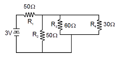
A
R1
B
R2
C
R3
D
R4
Video Solution
Text Solution
The correct Answer is:A
|
Answer
Step by step video & image solution for In the circuit shown , the resistances are given in ohms and the battery is assumed ideal with emf equal to 3.0 volts The resistor that dissipates the most power is by Physics experts to help you in doubts & scoring excellent marks in Class 12 exams.
Updated on:21/07/2023
Related Playlists
- BOOK - MOTIONCHAPTER - CURRENT ELECTRICITYEXERCISE - EXERCISE -2 (Level-1) SECTION -F Electrical Instrument + Exp. Verifying ohm s law & Specific Resistance Using Meter Brige & Post Office + Potentiometer (EMF & Int . Res.)7videos
CURRENT ELECTRICITY
- BOOK - MOTIONCHAPTER - CURRENT ELECTRICITYEXERCISE - EXERCISE -2 (Level -II) SECTION -A Definition of Current , Current Density , Drift Velocity1videos
CURRENT ELECTRICITY
- BOOK - MOTIONCHAPTER - CURRENT ELECTRICITYEXERCISE - EXERCISE -2 (Level-1) SECTION C,D - Circuit theory , KCL & KVL, Battery , Grouping of cells14videos
CURRENT ELECTRICITY
- BOOK - MOTIONCHAPTER - CONSTRAINED MOTION EXERCISE - EXAMPLES12videos
CONSTRAINED MOTION
- BOOK - MOTIONCHAPTER - ELASTICITYEXERCISE - EXERCISE -360videos
ELASTICITY
Similar Practice Problems
- Question 1 - Select One
In the circuit shown below the resistance are given in ohms and the battery is assumed ideal with emf equal to 3.0 volts. The resistor that dissipates the most power is -
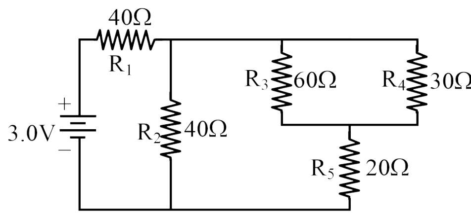 AR1BR2CR3DR4
 - Question 1 - Select One
In the circuit shown, the resistance are given ohms and the battery is assumed ideal with end equal to 3.0 volts. The resistance that dissipates the maximum power is
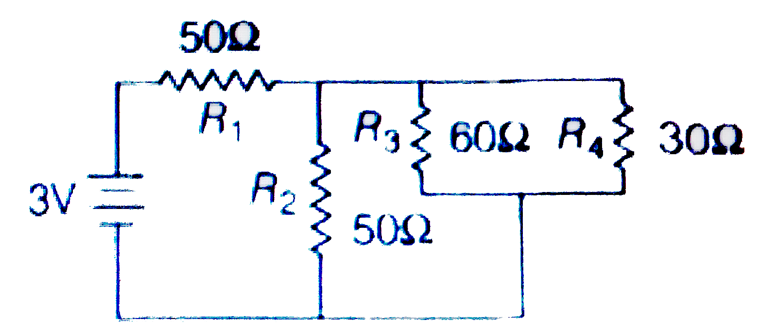 AR1BR2CR3DR4
 - Question 1 - Select One
In circuit shown below, the resistance are given in ohms and the battery is assumed ideal with emf equal to 3 volt The voltage across the resistance R4 is
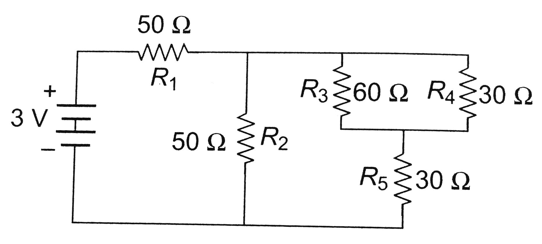 A0.4VB0.6VC1.2VD1.5V
 - Question 1 - Select One
In circuit show below, the resistances are given in ohms and the battery is assumed ideal with emf equal to 3 V. The voltage across the resistance R4 is :
 A0.4 VB0.6 VC1.2 VD1.5 V
 - Question 1 - Select One
In circuit show below, the resistances are given in ohms and the battery is assumed ideal with emf equal to 3 V. The voltage across the resistance R4 is :
 A0.4 VB0.6 VC1.2 VD1.5 V
 - Question 1 - Select One
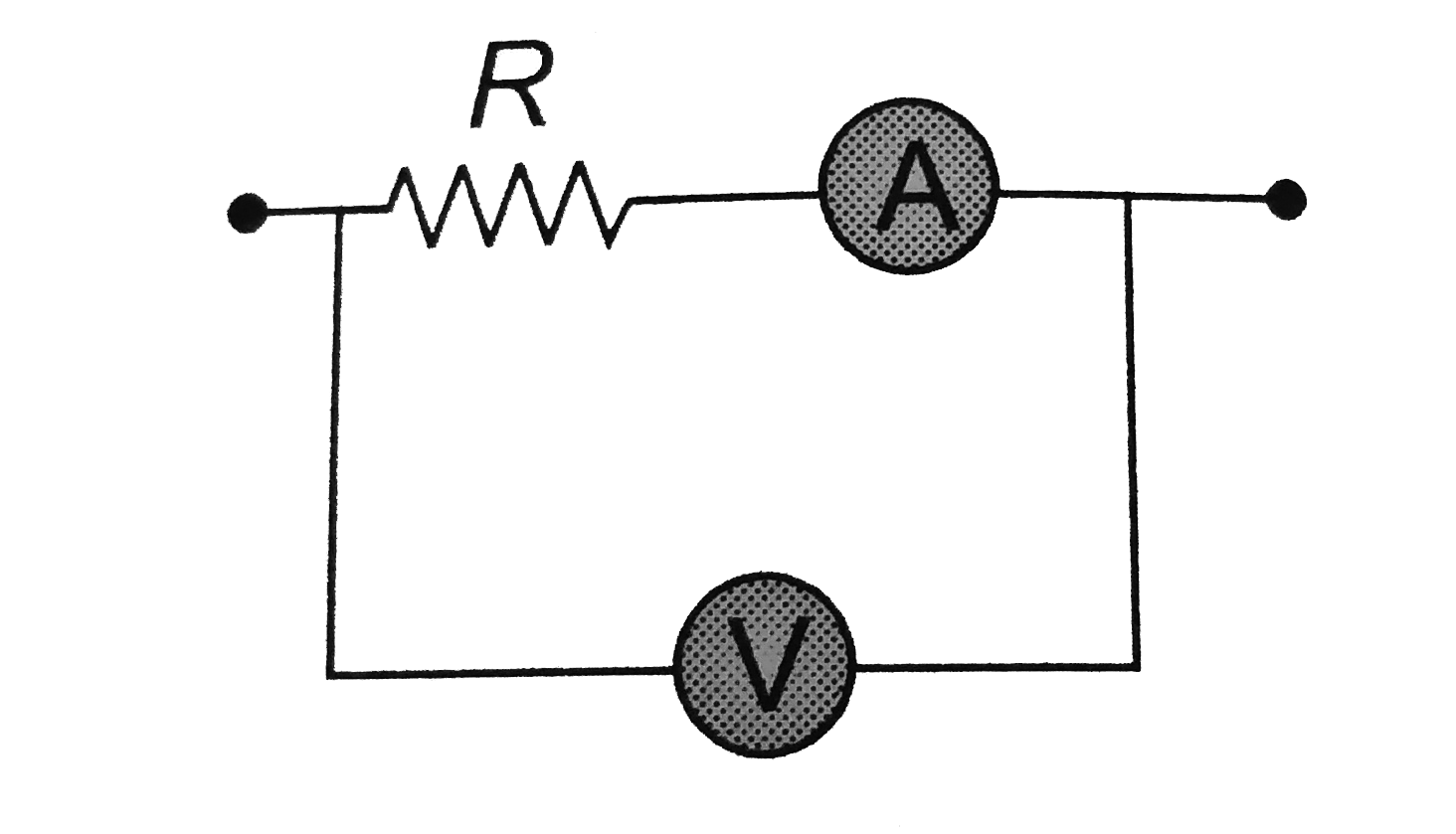
In the circuit shown the resistance of voltmeter is 10000ohm and that of ammeter is 20ohm. The ammeter reading is 0.10amp and voltmeter reading is 12 volts. Then R is equal to
 A122ΩB140ΩC116ΩD100Ω
 - Question 1 - Select One
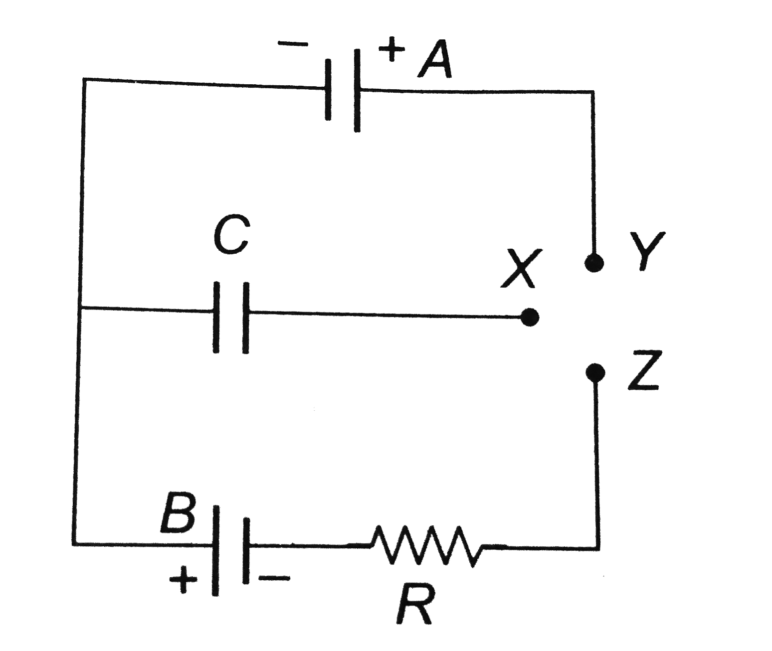
In the circuit shown the cells are ideal and of equal emfs, the capacitance of the capacitor is C and the resistance of the resistor is R. X is first joined to Yand then to Z. After a long time, the total heat produced in the resistor will be
 Aequal to the energy finally stored in the capacityBhalf of the energy finally stored in the capacitorCtwice the energy finally stored in the capacitorD3 times the energy finally stored in the capacitor
 - Question 1 - Select One
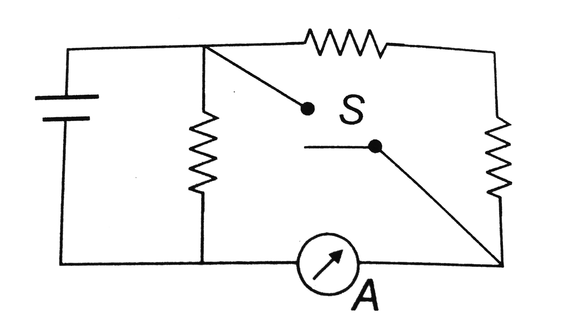
In the circuit shown, the reading of the Ammter is doulbed after the switch is closed. Each resistor has a resistance =1Ω and the ideal cell has an e.m.f. =10V. Then the ammeter has a resistance equal to
 A2ΩB1ΩC2.5ΩDNone
Similar Questions
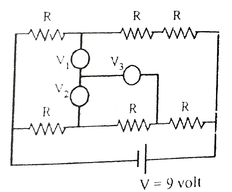
In the circuit shown below, all the three voltmeters are identical and have very high resistance. Each resistor has the same resistance The voltage of the ideal battery shown is 9 V Find the reading of voltmeter V3 (in volts)
 View Solution
In the circuit shown power dissipated in 12Ωresistance is 6 watt. What is the power dissipated in the 8Ω resistance.
View Solution

