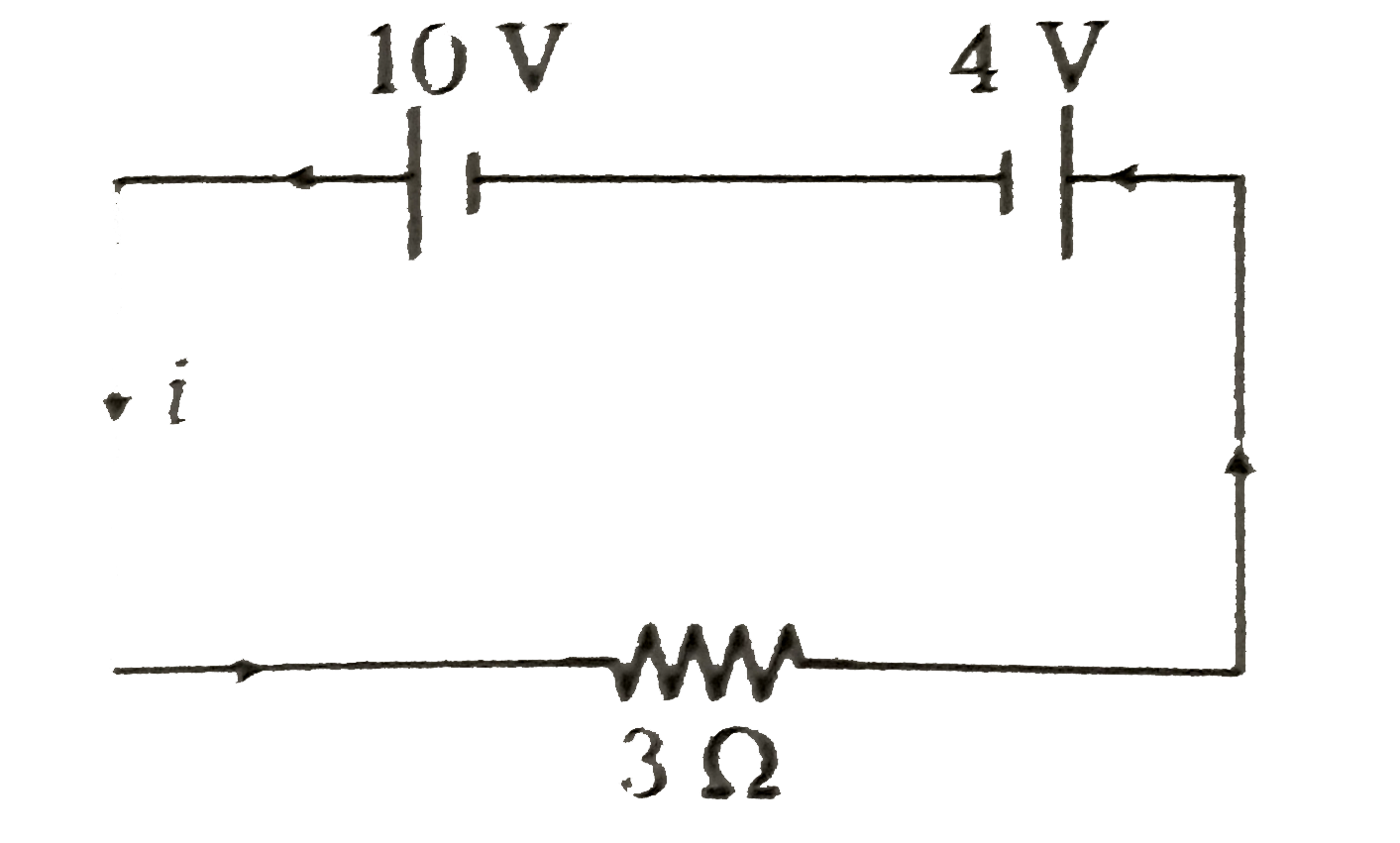
You are given two circuits as shown in following figure. The logic operation carried out by the two circuit are respectively :-
_E01_415_Q01.png)
Video Solution
Text Solution
In both the given circuits, A and B are the inputs and Y is the output.
The output of the left NAND gate will be , as shown in the following figure. 
Hence, the output of the combination of the two NAND gates is given as:
Hence, this circuit functions as an AND gate.
(b) is the output of the upper left of the NAND gate and is the output of the lower half of the NAND gate, as shown in the following figure. 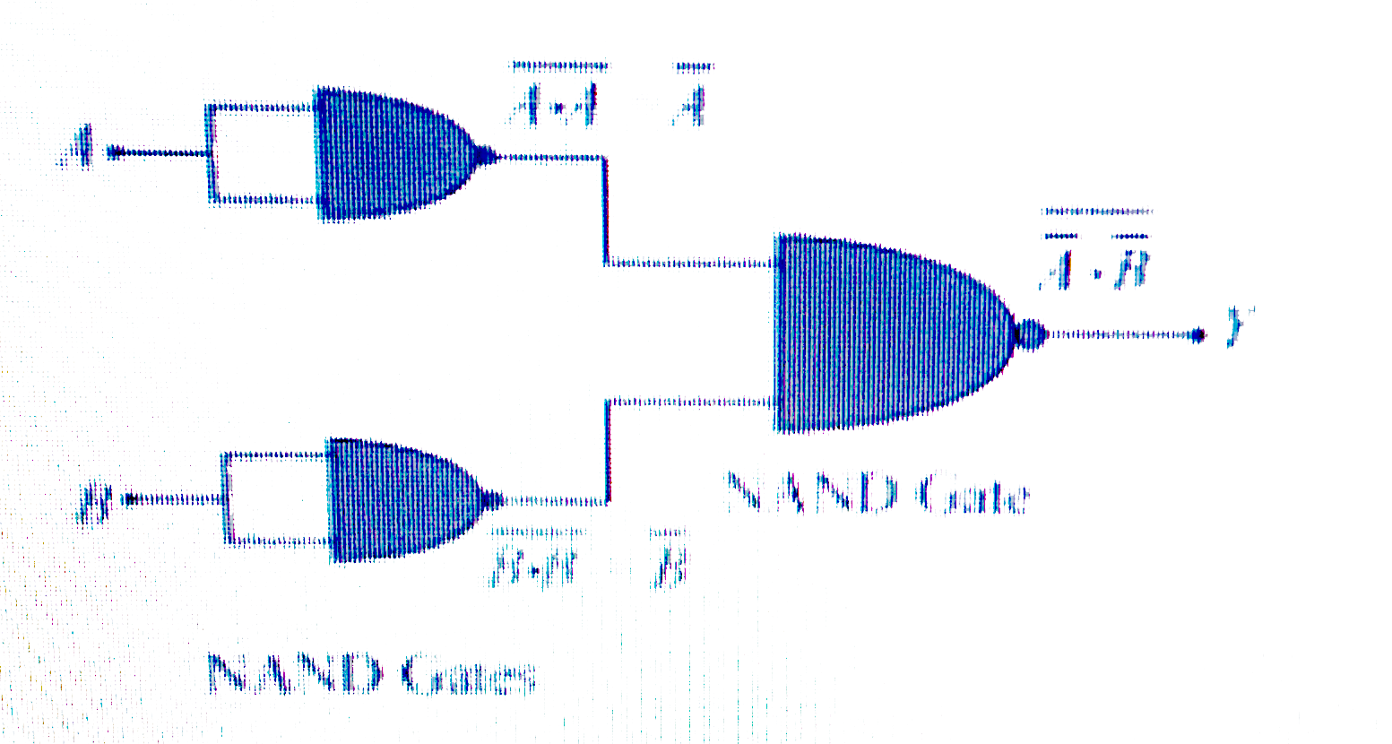
Hence, the output of the combination of the NAND gates will be given as:
Hence, this circuit functions as an OR gate.
|
Topper's Solved these Questions
- SEMICONDUCTOR ELECTRONICS MATERIALS DEVICES AND SIMPLE CIRCUITSBook:NCERTChapter:SEMICONDUCTOR ELECTRONICS MATERIALS DEVICES AND SIMPLE CIRCUITSExercise:Exercise
Explore 15 Videos
- RAY OPTICS AND OPTICAL INSTRUMENTSBook:NCERTChapter:RAY OPTICS AND OPTICAL INSTRUMENTSExercise:Exercise
Explore 32 Videos
- WAVE OPTICS Book:NCERTChapter:WAVE OPTICS Exercise:Exercise
Explore 21 Videos
Similar Questions
Knowledge Check
For the circuit shown in the following figure.
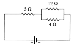 AThe heat dissipated in 4Ω resistance is more than that dissipated in 12Ω resistanceBMaximum heat is dissipated in 3Ω resistanceCThe heat dissipated in 12Ω resistance is more than that dissipated in 4Ω resistanceDThe power dissipated in 3Ω resistance is 18 W
For the circuit shown in the following figure,
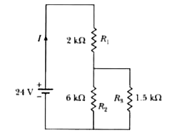 AThe current I through the battery is 7.5 mABThe potential difference across R3 is 18 VCRatio of powers dissipated in R1andR2 is 3DIf R1andR2 are interchanged, magnitude of the power dissipated in R3 will decrease by a factor of 9
For the circuit shown in the following figure, the
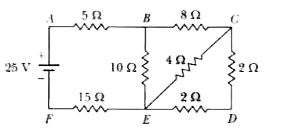 APotential difference between points B and E is 5 VBPotential difference between points A and B is 10 VCCurrent in the 4Ω resistor is 0.25ADCurrent in the 4Ω resistor is 0.5 A
Identify the logic operation carried out by the following circuit

View SolutionIdentify the logic operation performed by the circuit given here.

View Solution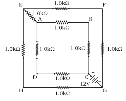
In the given circuit (as shown in the figure)
View SolutionConsider the circuit shown in the following figure.
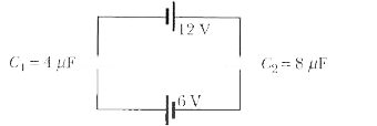
View SolutionIn the two circuits shown in figure
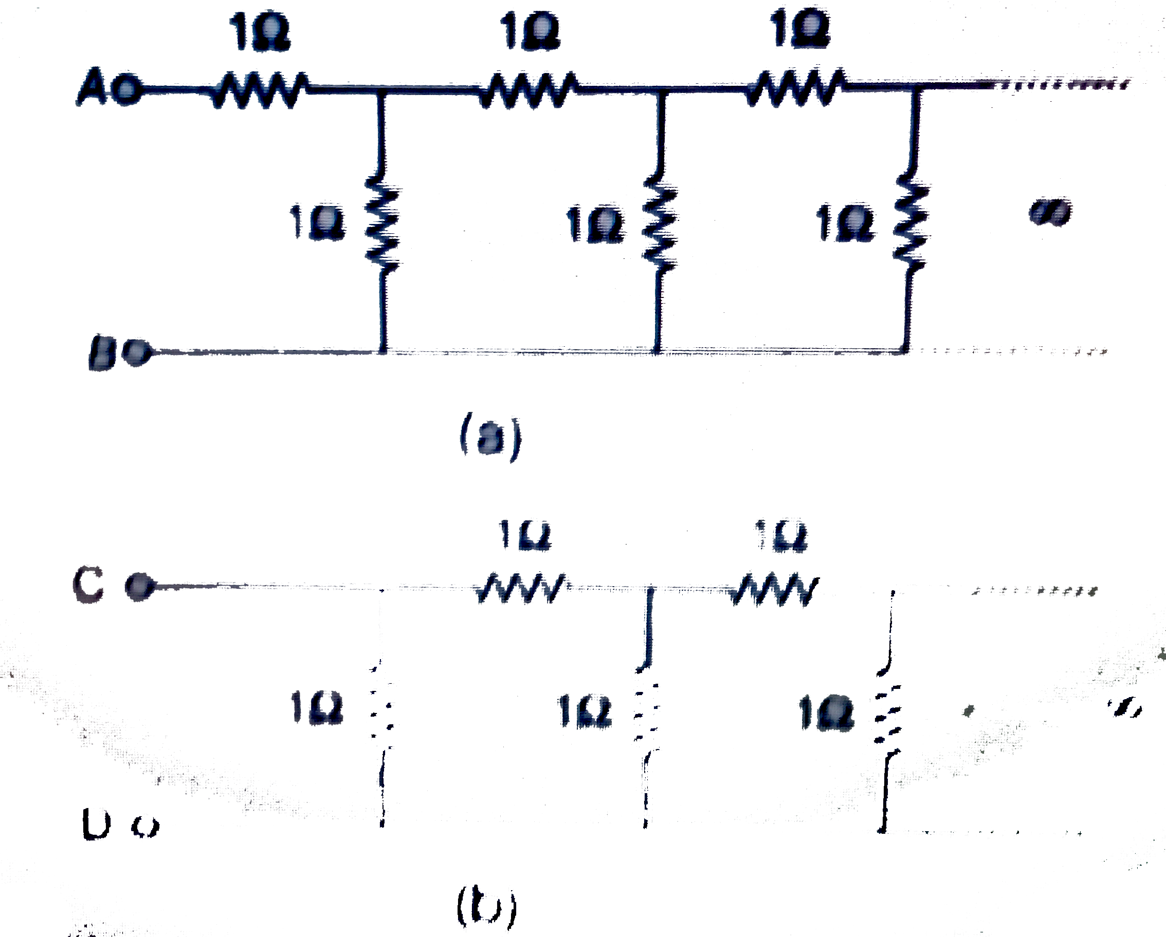
View Solution


