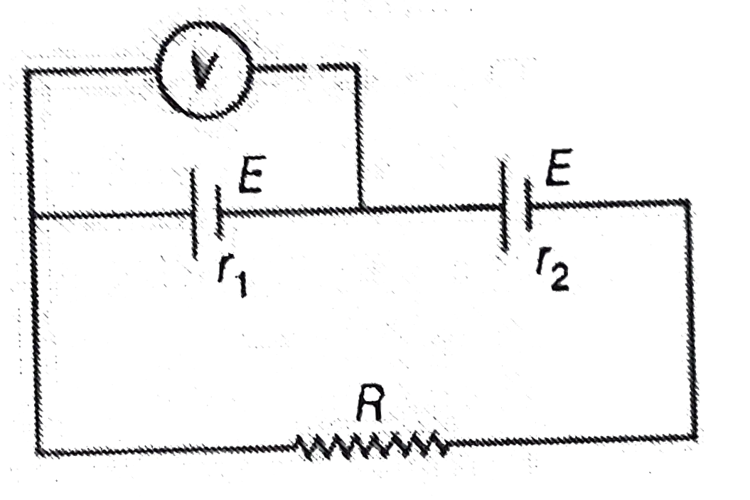
In the following figure, the reading of an ideal voltmeter V is zero. Then, the relation between R, r1 and r2 is
R=r2−r1
R=r1−r2
R=r1+r2
R=r1r2r1+r2
The correct Answer is:B
l=2Er1+r2+R
V1=E−lr1=0
⇒ l=E/r1
E=2Er1r1+r2+R
r1+r2+R=2r1
⇒ R=r1+r2
Topper's Solved these Questions
- CURRENT ELECTRICITYBOOK - BITSAT GUIDECHAPTER - CURRENT ELECTRICITYEXERCISE - Bitsat Archives
26 Videos
- CATHODE RAY, PHOTOELECTRIC EFFECT AND X-RAYSBOOK - BITSAT GUIDECHAPTER - CATHODE RAY, PHOTOELECTRIC EFFECT AND X-RAYSEXERCISE - BITSAT Archives
6 Videos
- ELECTRIC CAPACITORBOOK - BITSAT GUIDECHAPTER - ELECTRIC CAPACITOREXERCISE - BITSAT archives
6 Videos
Similar Questions
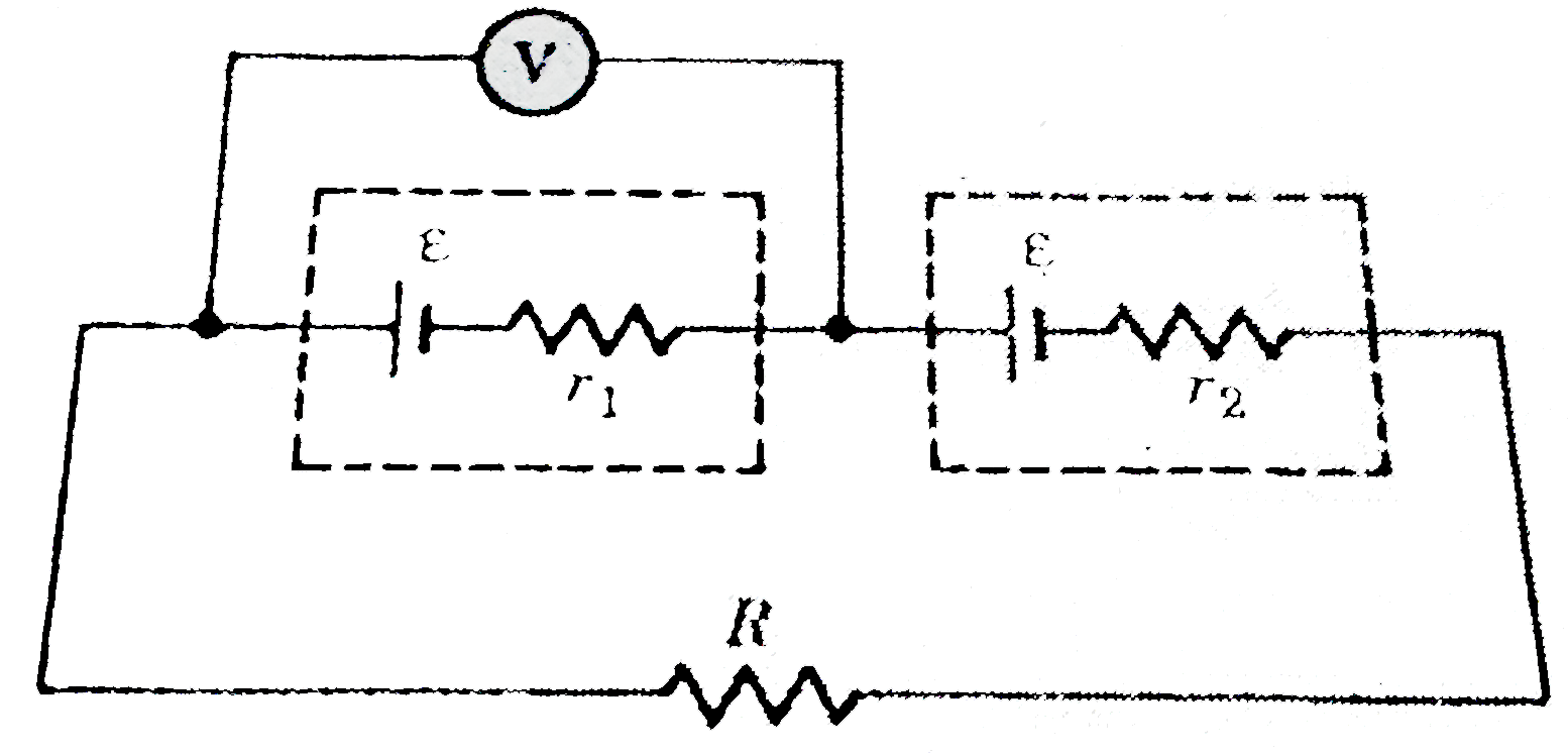
Two cells of same emf ε, but different internal resistances r1 and r2 are connected to an external resistance R, as shown. The voltmeter V reads zero. Find R in terms of r1 and r2, and the voltage across the cell of internal resistance r2.
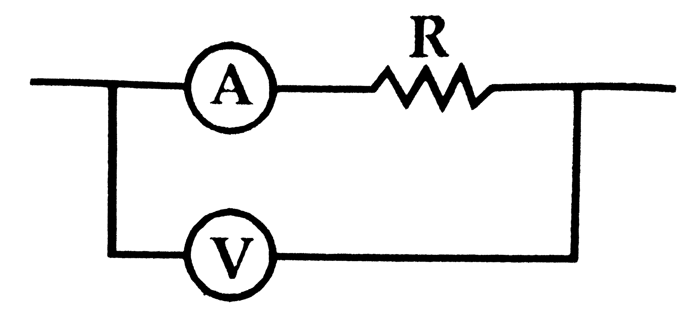
View SolutionIn given figure the ammeter A reads 5 A and voltmeter V reads 40 V. The actual value of resistance R is
View Solution
Knowledge Check
In Fig. two cells have equal emf E but internal resistances are r1andr2. If the reading of the voltmeter is zero, then relation between R, r1andr2 is
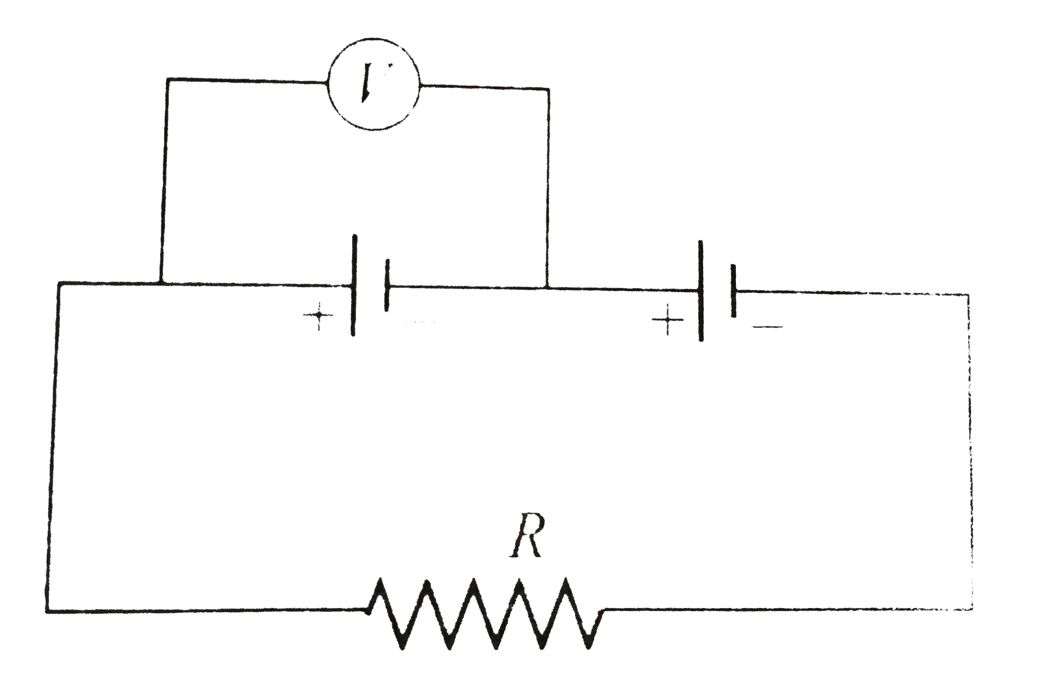 AR=r1−r2BR=r1+r2C2r1−r2Dr1r2
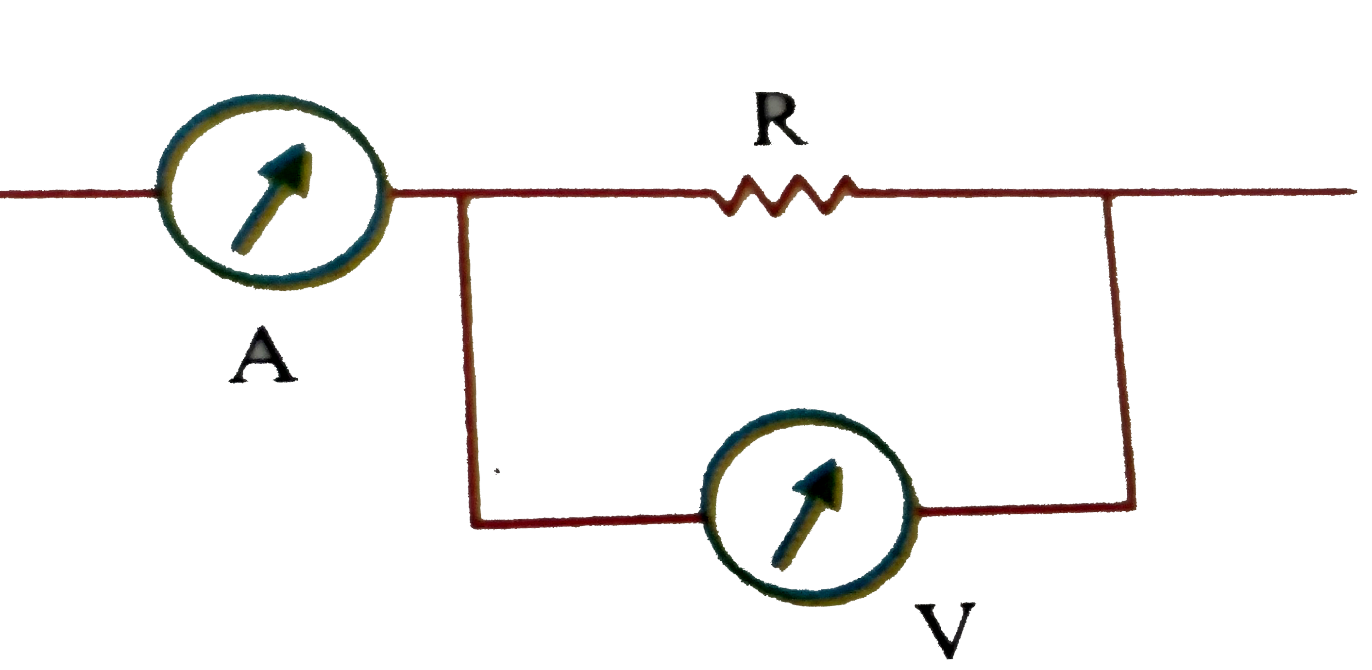
In the following diagram ammeter reading is 4A, voltmeter reading is 20V, the value of R isA>5ΩB<5ΩC=5ΩD≤5ΩConsider the circuit shown in the figure, the cell is ideal. The readings of the ideal voltmeters V1 and V2 in volts are respectively.
 A2,0B0,2C0,0D2,2
If R is a symmetric relation on a set A , then write a relation between R and R−1 .
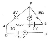
View SolutionFind the reading of ammeter A and voltmeter V shown in the figure assuming the instruments to be ideal
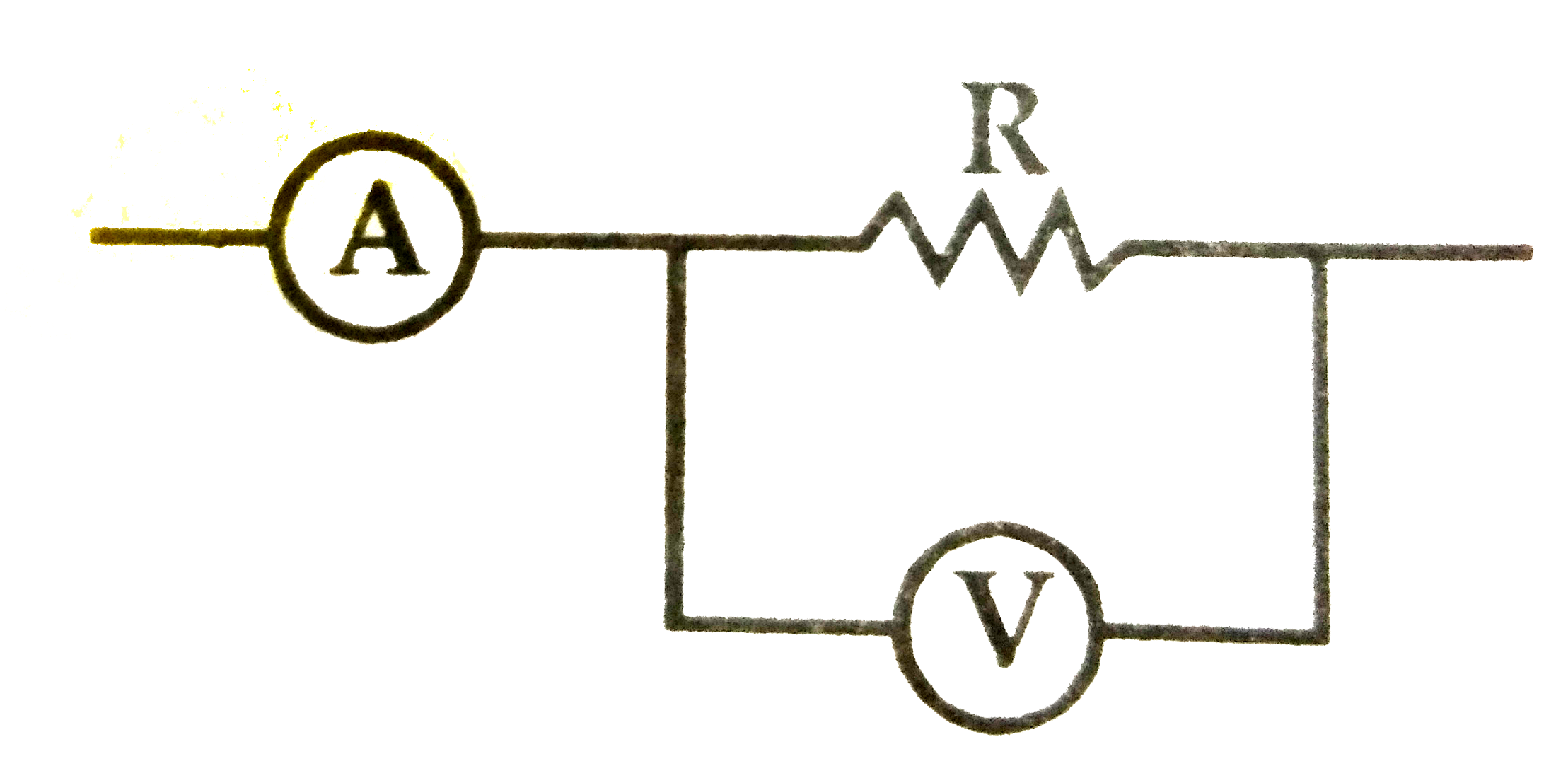
View SolutionIn given figure an ammeter reads 5 A and voltmeter reads 40 V. The actual value of resistance R is
View Solution[" A non-ideal voltmeter and a non-ideal ammeter are connected as shown in the figure.The reading of "],[" the voltmeter is "20V" and that of the ammeter is "4A" .The value of "R" is : "],[qquad (A)/(0)]
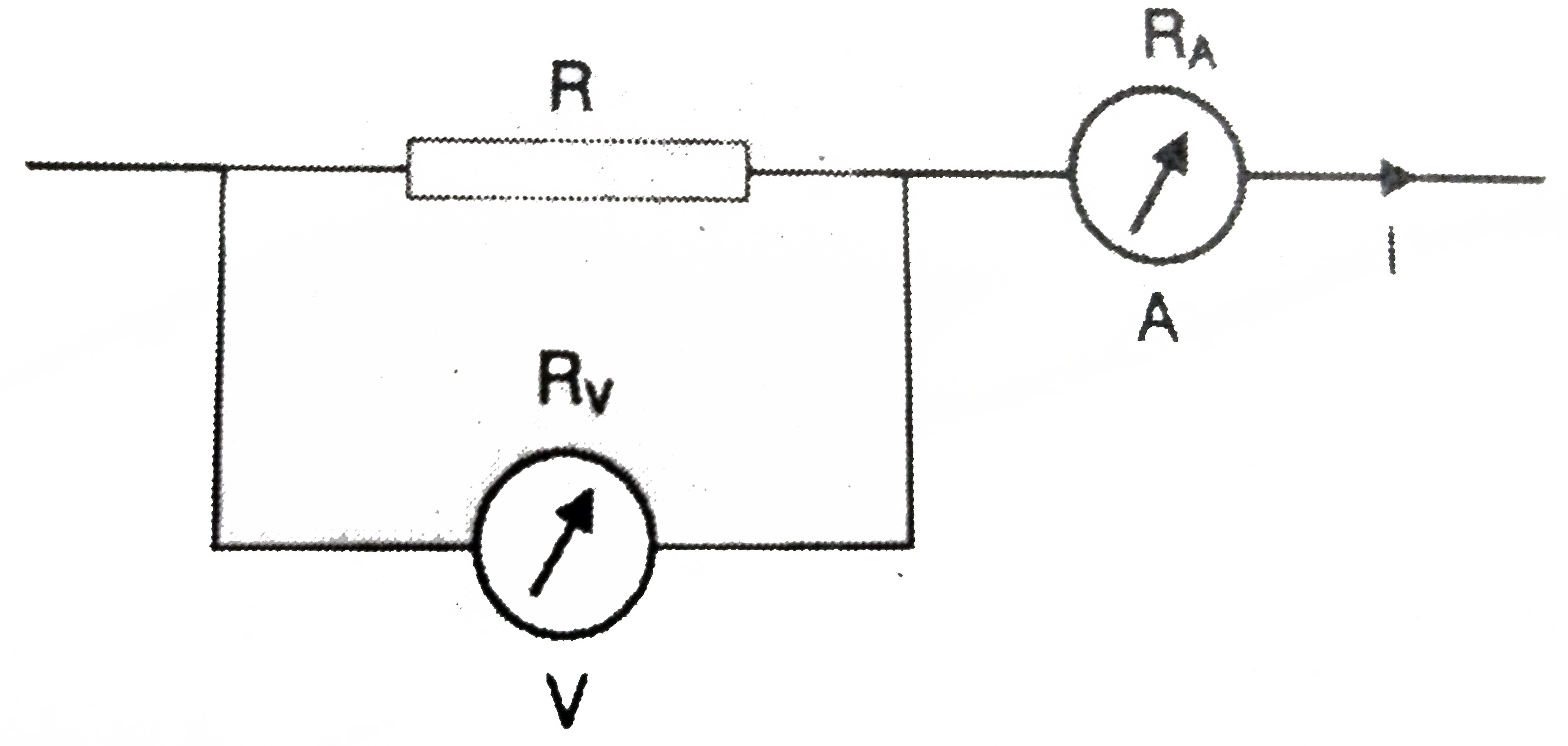
View SolutionLet V and I be the readings of the voltmeter and the ammeter respectively as shown in the figure. Let RV and RA be their corresponding resistancce Therefore,
View Solution
