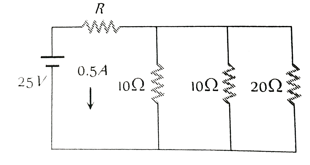
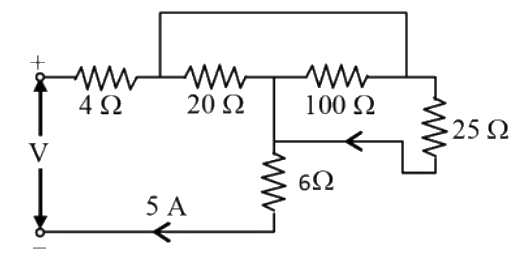
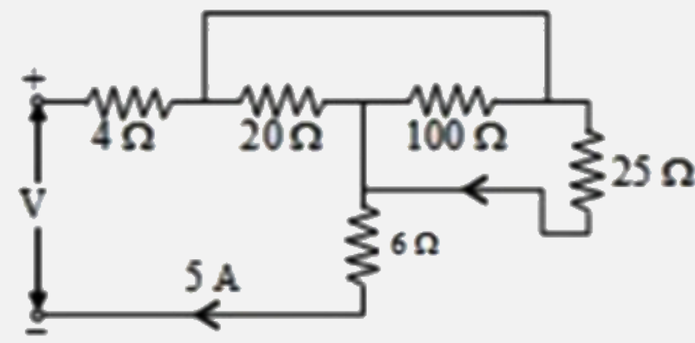
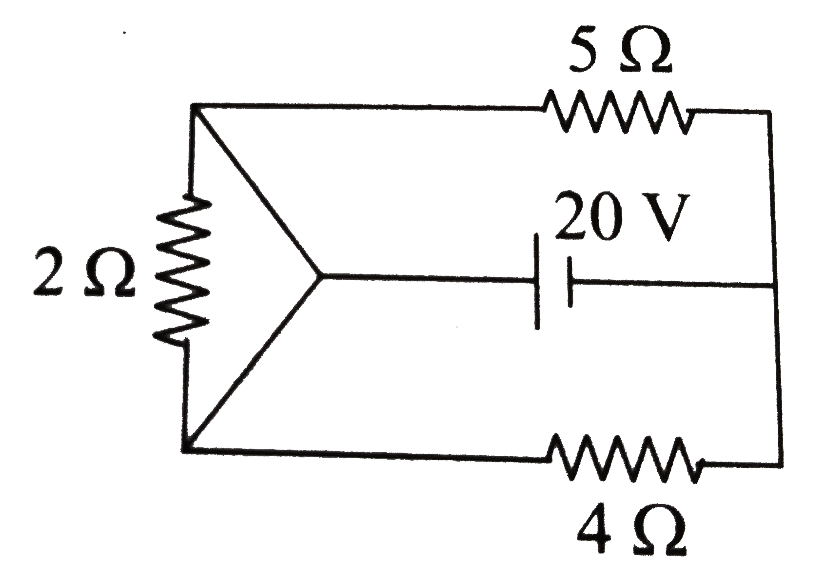
In the circuit shown in figure , V must be
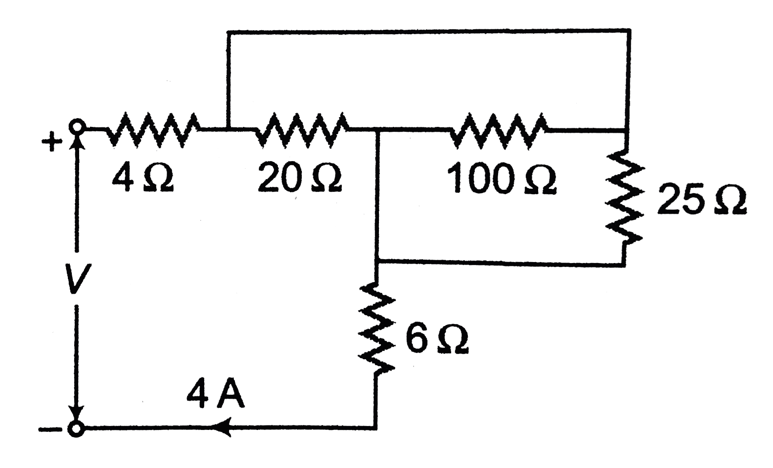
A
50 V
B
80 V
C
100 V
D
1290 V
Video Solution
Text Solution
The correct Answer is:B
|
Answer
Step by step video, text & image solution for In the circuit shown in figure , V must be by Physics experts to help you in doubts & scoring excellent marks in Class 12 exams.
Updated on:21/07/2023Topper's Solved these Questions
- CURRENT ELECTRICITYBook:DC PANDEYChapter:CURRENT ELECTRICITYExercise:B. Assertion and reason
Explore 18 Videos
- CURRENT ELECTRICITYBook:DC PANDEYChapter:CURRENT ELECTRICITYExercise:Match the columns
Explore 4 Videos
- CURRENT ELECTRICITYBook:DC PANDEYChapter:CURRENT ELECTRICITYExercise:Check point
Explore 70 Videos
- COMMUNICATION SYSTEMBook:DC PANDEYChapter:COMMUNICATION SYSTEMExercise:Subjective
Explore 11 Videos
- ELECTROMAGNETIC INDUCTIONBook:DC PANDEYChapter:ELECTROMAGNETIC INDUCTIONExercise:Medical entrances gallery
Explore 25 Videos
Similar Questions
Knowledge Check
For the circuit shown in figure,
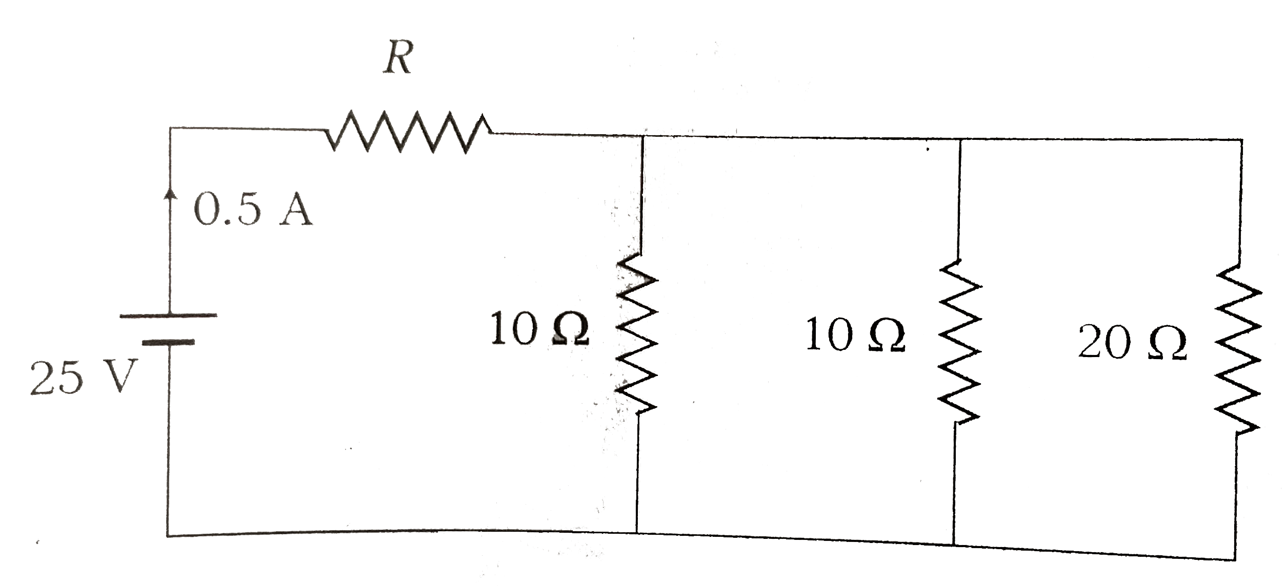 Aresistance R=46ΩBcurrent through 20Ω resistance is 0.1ACpotential difference across the middle resistance is 2 VDAll of the above are true
For the circuit shown in figure
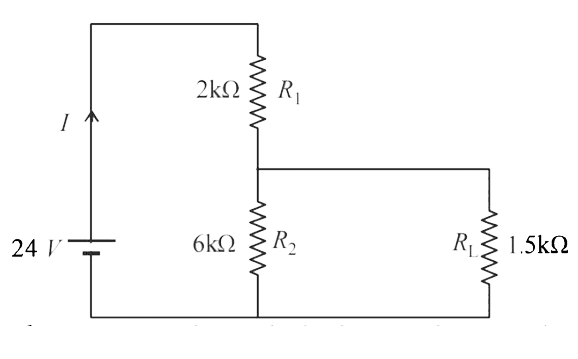 Athe current I through the batter is 7.5 mA.Bthe potential difference across R_L is 18V.Cratio of powers dissipated in R1andR2 is 3Dif R1andR2 are interchanged, magnitude of the power dissipated in RL will decrease by a factor of 9.
In the circuit shown in the figure,
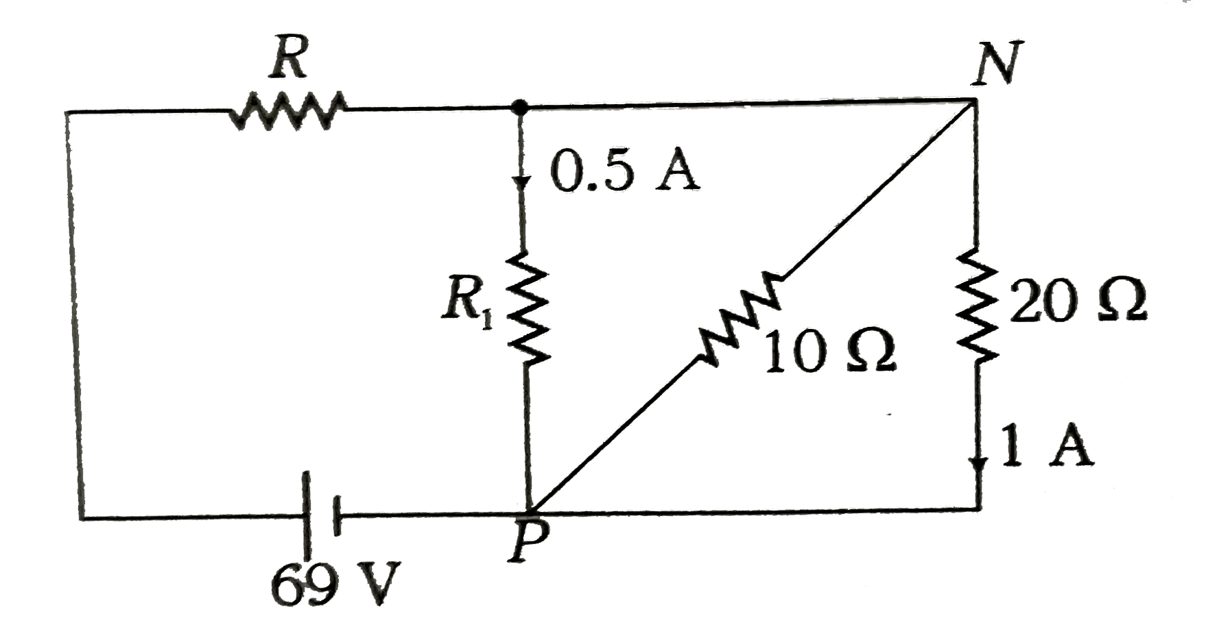 AThe current through NP is 0.5 ABThe value of R1=40ΩCThe value of R =14ΩDsThe potential difference across R = 49 V



 .
. 
