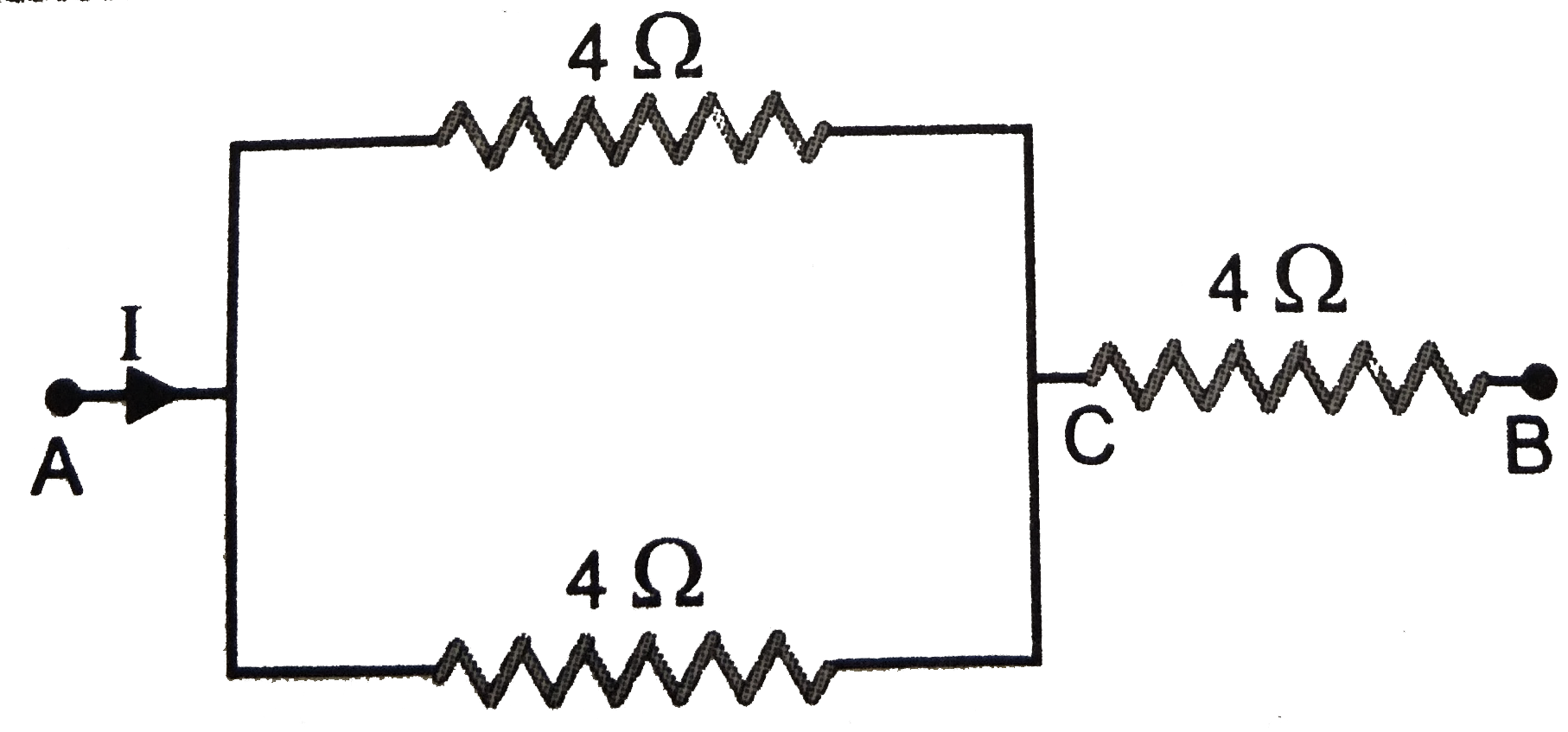
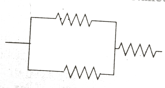
In the circuit shown in Fig.6.1, each of the three resistors of 4Ω can have a maximum power of 20W (otherwise it will melt). What maximum power can the whole circuit take?
Step by step video & image solution for In the circuit shown in Fig.6.1, each of the three resistors of 4Omega can have a maximum power of 20W (otherwise it will melt). What maximum power can the whole circuit take? by Physics experts to help you in doubts & scoring excellent marks in Class 12 exams.
Updated on:21/07/2023Topper's Solved these Questions
Similar Questions
Knowledge Check
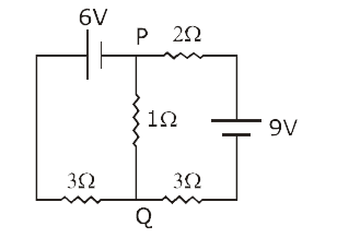
In the circuit shown, the currect in the 1Ω resistor
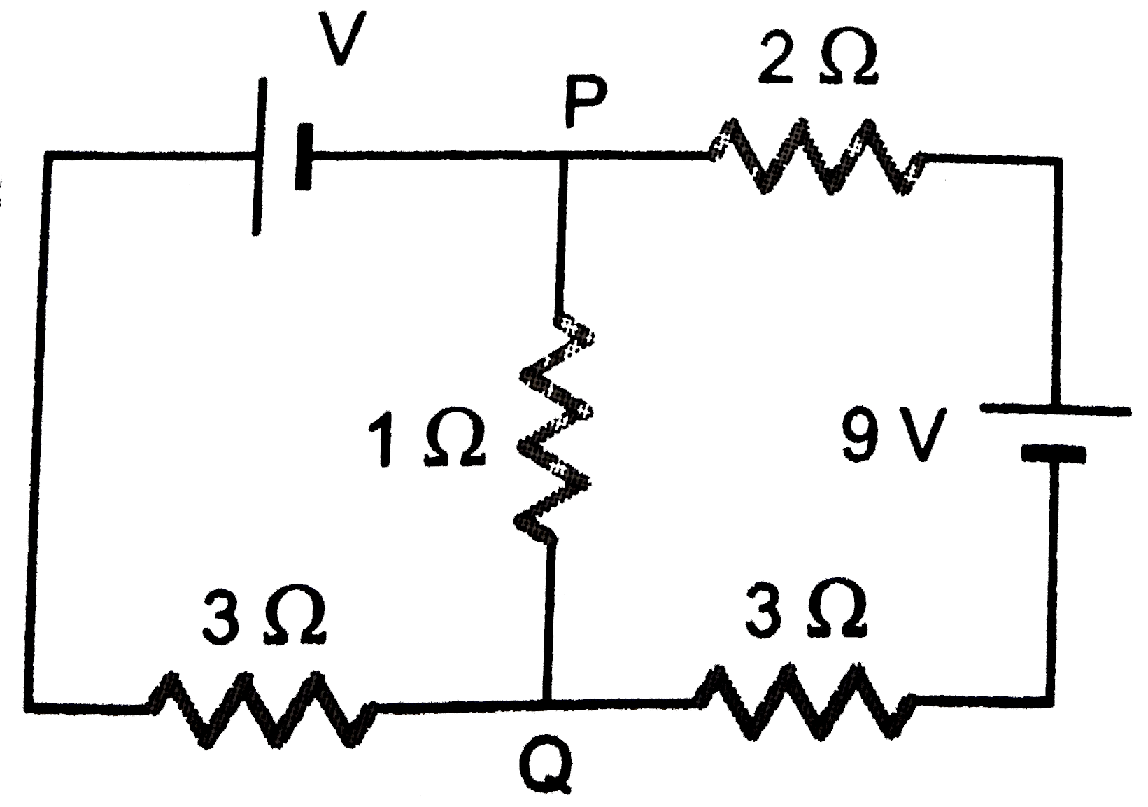 A1.3A from P to QB0AC0.13A from Q to PD0.13A from P to Q
For the circuit shown in the figure, the current in the 4Ω resistor is
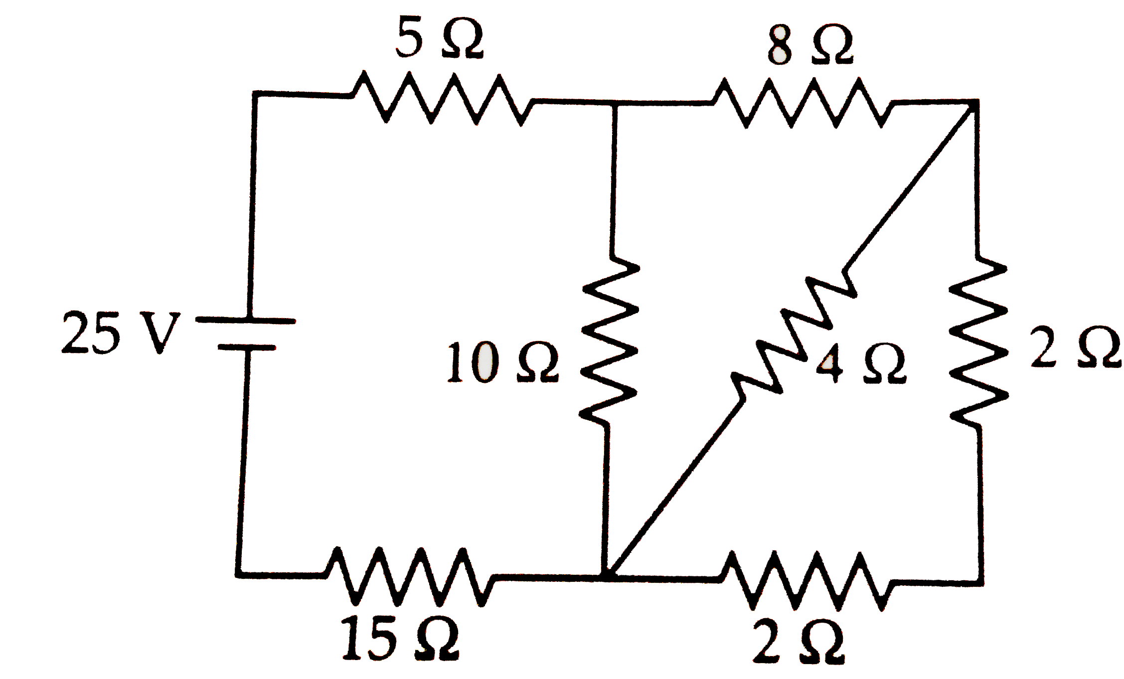 A0.5AB0.25AC1AD1.5A
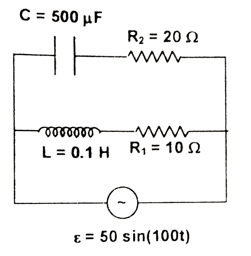
In the circuit shown the average power developed in the resistor R1 isA31.25 WB62.50 WC125 WD250 W
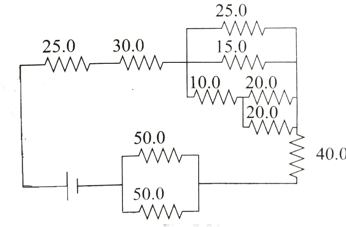
In the circuit shown in fig. 7.24 , all the resistors are rated at a maximum power of 1.00W. What is the maximum emfε that the battery can have without burning up any of the resistors?
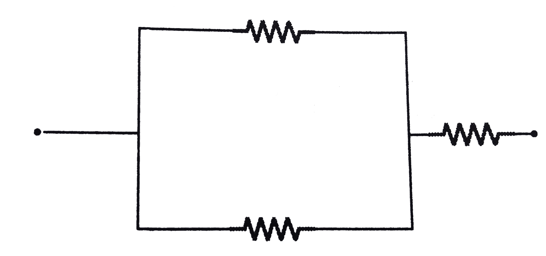
View SolutionEach of three resistors in figure has a resistance of 2.4Ω and can dissipate a maximum of 36 W without becoming excessively heated. What is the maximum power the circuit can dissipate?
View Solution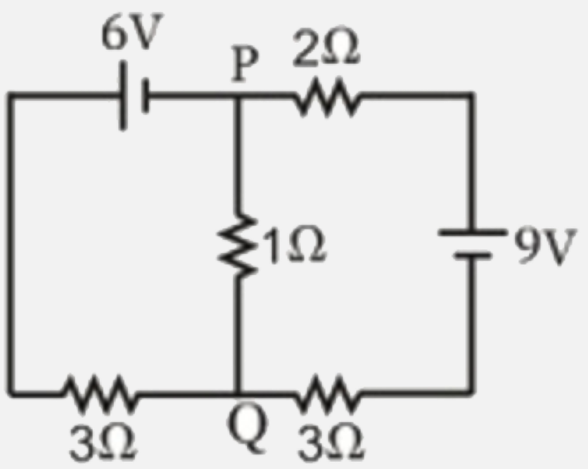
In the circuit shown, what is the current (in A) in the 1Ω resistor?
View SolutionEach of three resistors in fig. 7.12 has a resistance of 2Ω and can dissipate a maximum of 18W without becoming excessively heated. Find the maximum power the circuit can dissipate.
View SolutionIn the following figures, each of the three resistances, the rating of 24 W and resistance of 6Ω. Find the maximum power rating of the circuit.

View Solution

