In the circuit shown, both cells are ideal and of fixed emf, the resistance of resistance has fixed resistance and the resistance of resistor can be varied (but the value of is not zero). Then:
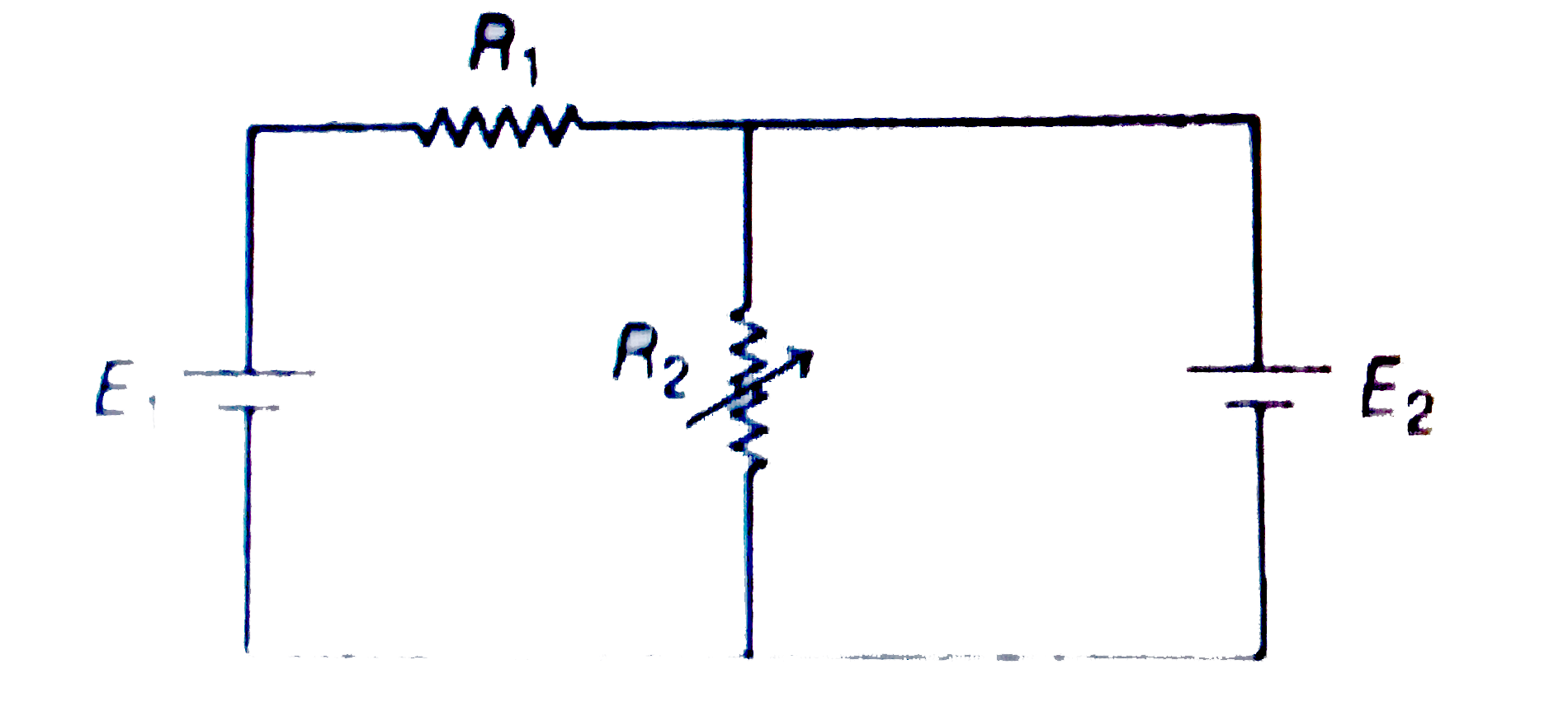
The electric power delivered to resistor of resistance is independent of
Electric power delivered by is independent of
Electric power delivered by is dependent on
Electric power delivered to is dependent on
The correct Answer is:A, B
Step by step video, text & image solution for In the circuit shown, both cells are ideal and of fixed emf, the resistance of resistance R_(1) has fixed resistance and the resistance of resistor R_(2) can be varied (but the value of R_(2) is not zero). Then: by Physics experts to help you in doubts & scoring excellent marks in Class 11 exams.
Updated on:21/07/2023Topper's Solved these Questions
Similar Questions
Knowledge Check
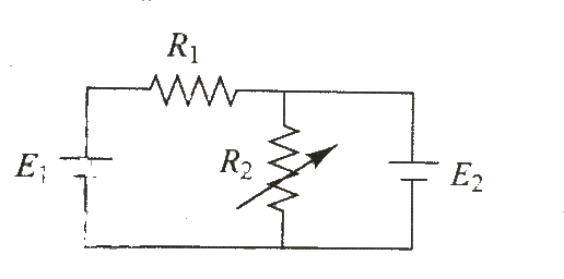
Statement I : In the circuit in Fig.7.46, both cells are ideal and of fixed emf, the resistor R1 has fixed resistance and the resistance of resistor R2 can be varied ( but R2 is always non zero). Then the electric power delivered to the resistor of resistance R1 is independent of the value of resistance R2.
Statement II: If potential difference across a fixed resistance is unchanged , the poweer delivered to the resistor remains constant.
 AStatement I is True , Statement II is True , Statement II is a correct explanation for Statement I.BStatement I is True, Statement II is True , Statement II is NOT a correct explanation for statement I.CStatement I is True , Statement is False.DStatement I is False, Statement II is True.
In the circuit shown below, the ammeter reading is zero. Then, the value of the resistance R is
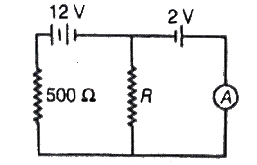 A50ΩB100ΩC200ΩD400Ω
In the circuit shown below, the ammeter reading is zero. Then, the value of the resistance R is
 A50ΩB100ΩC200ΩD400Ω
A cell develops the same power across two resistances R1 and R2 separately. The internal resistance of the cell is
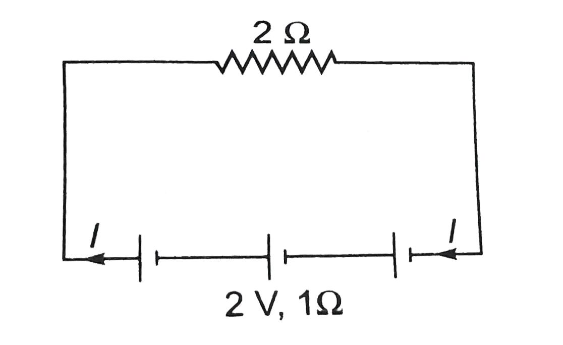
View SolutionIn the electric circuit shown each cell has an emf of 2 V and internal resistance of 1Ω. The external resistance is 2Ω . The value of the current is (in A)
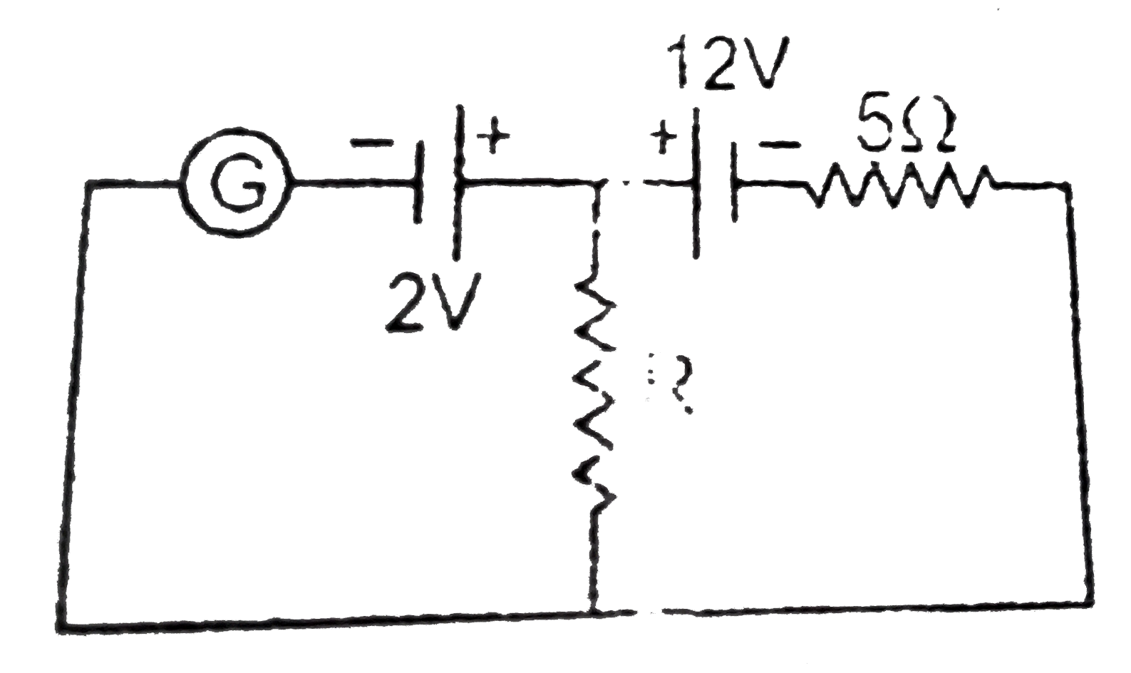
View SolutionIn the circuit shown, the galvanometer shows zero current. The value of resistance R is :
View SolutionIn the circuit shown in figure resistance of each wire is r. Net resistance across

View SolutionIn the circuit shown in the given figure, the resistances R1andR2 are respectively

View Solution


