In the given circuit, find the current through the 5mH inductor in steady state.
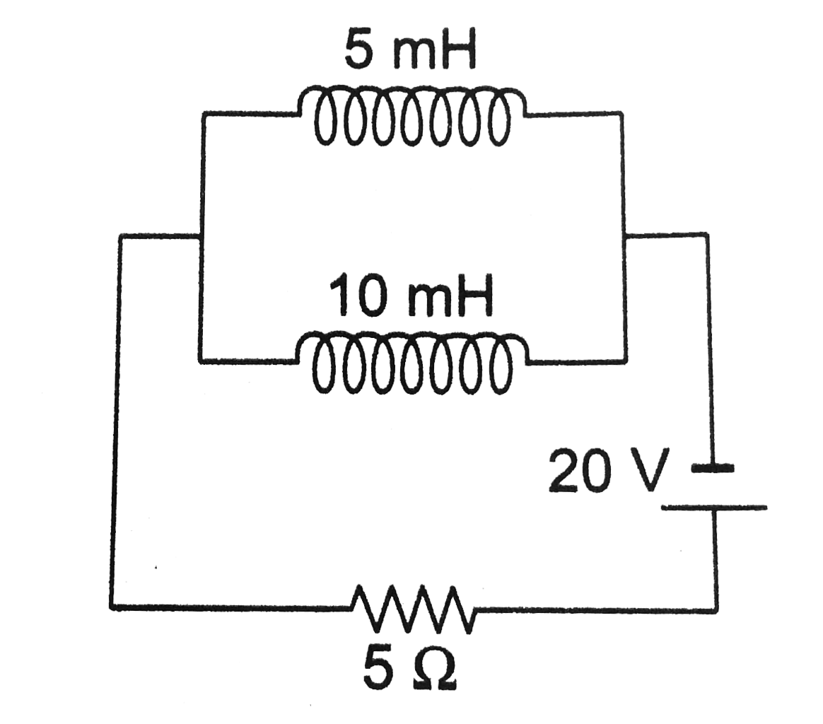
The correct Answer is:83A
Step by step video, text & image solution for In the given circuit, find the current through the 5 mH inductor in steady state. by Physics experts to help you in doubts & scoring excellent marks in Class 12 exams.
Updated on:21/07/2023Topper's Solved these Questions
- ELECTROMAGNETIC INDUCTION AND ALTERNATING CURRENTBOOK - PHYSICS GALAXY - ASHISH ARORACHAPTER - ELECTROMAGNETIC INDUCTION AND ALTERNATING CURRENTEXERCISE - Practice Exercise 5.5
7 Videos
- ELECTROMAGNETIC INDUCTION AND ALTERNATING CURRENTBOOK - PHYSICS GALAXY - ASHISH ARORACHAPTER - ELECTROMAGNETIC INDUCTION AND ALTERNATING CURRENTEXERCISE - Practice Exercise 5.6
8 Videos
- ELECTROMAGNETIC INDUCTION AND ALTERNATING CURRENTBOOK - PHYSICS GALAXY - ASHISH ARORACHAPTER - ELECTROMAGNETIC INDUCTION AND ALTERNATING CURRENTEXERCISE - Practice Exercise 5.3
13 Videos
- CURRENT ELECTRICITYBOOK - PHYSICS GALAXY - ASHISH ARORACHAPTER - CURRENT ELECTRICITYEXERCISE - All Questions
389 Videos
- ELECTROSTATICSBOOK - PHYSICS GALAXY - ASHISH ARORACHAPTER - ELECTROSTATICSEXERCISE - Unsolved Numberical Problems
73 Videos
Similar Questions
Knowledge Check
In the figure, the steady state current through the inductor will be
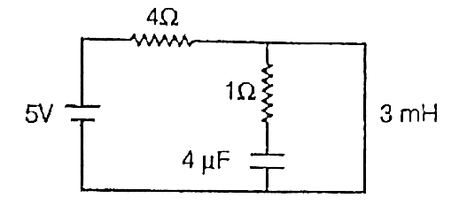 AzeroB1AC1.25ADCannot be determined
In the given circuit, with steady current, the potential of point A must be
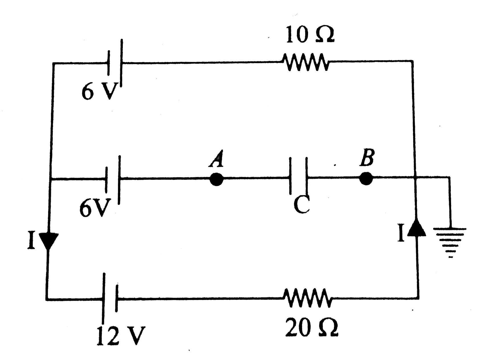 A1 VB3 VC4 VD2 V
In the given circuit, find the potential differece across the 6μf capacitor in steady state.
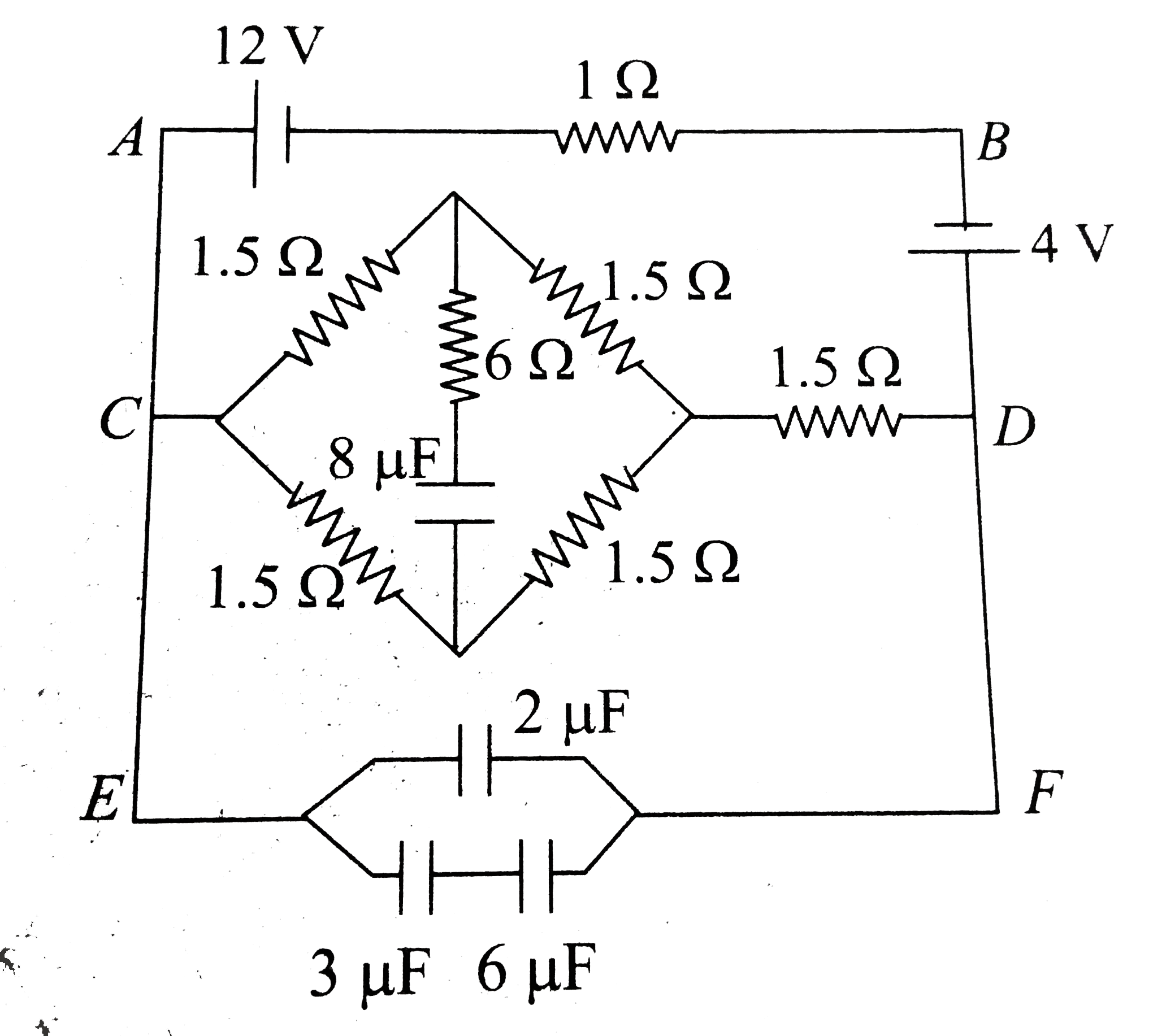 A4 VB2 VC6 VDnone of these
If an ideal diode is used in the given circuit, find the current through each resistance
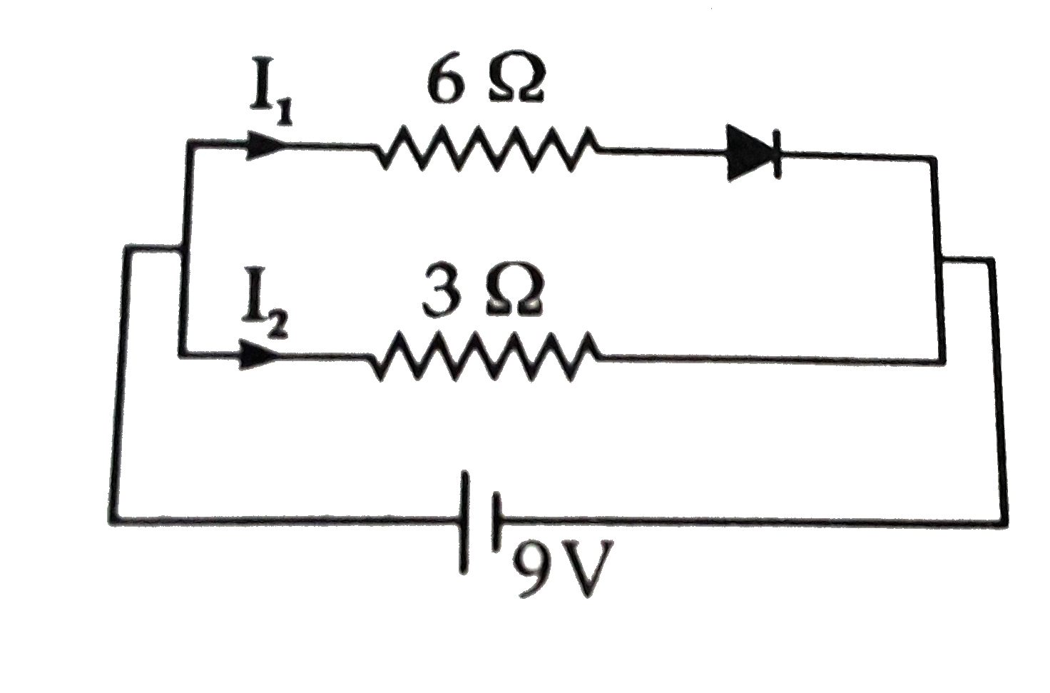
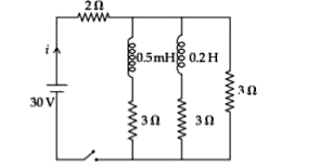
View SolutionFor the given circuit the current i through the battery when the key in closed and the steady state has been reached is _______ .
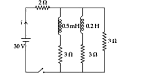
View SolutionFor the given circuit the current i through the battery when the key in closed and the steady state has been reached is _______ .
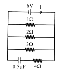
View SolutionIn the given circuit diagram, in the steady state the current through the battery and the charge on the capacitor respectively are
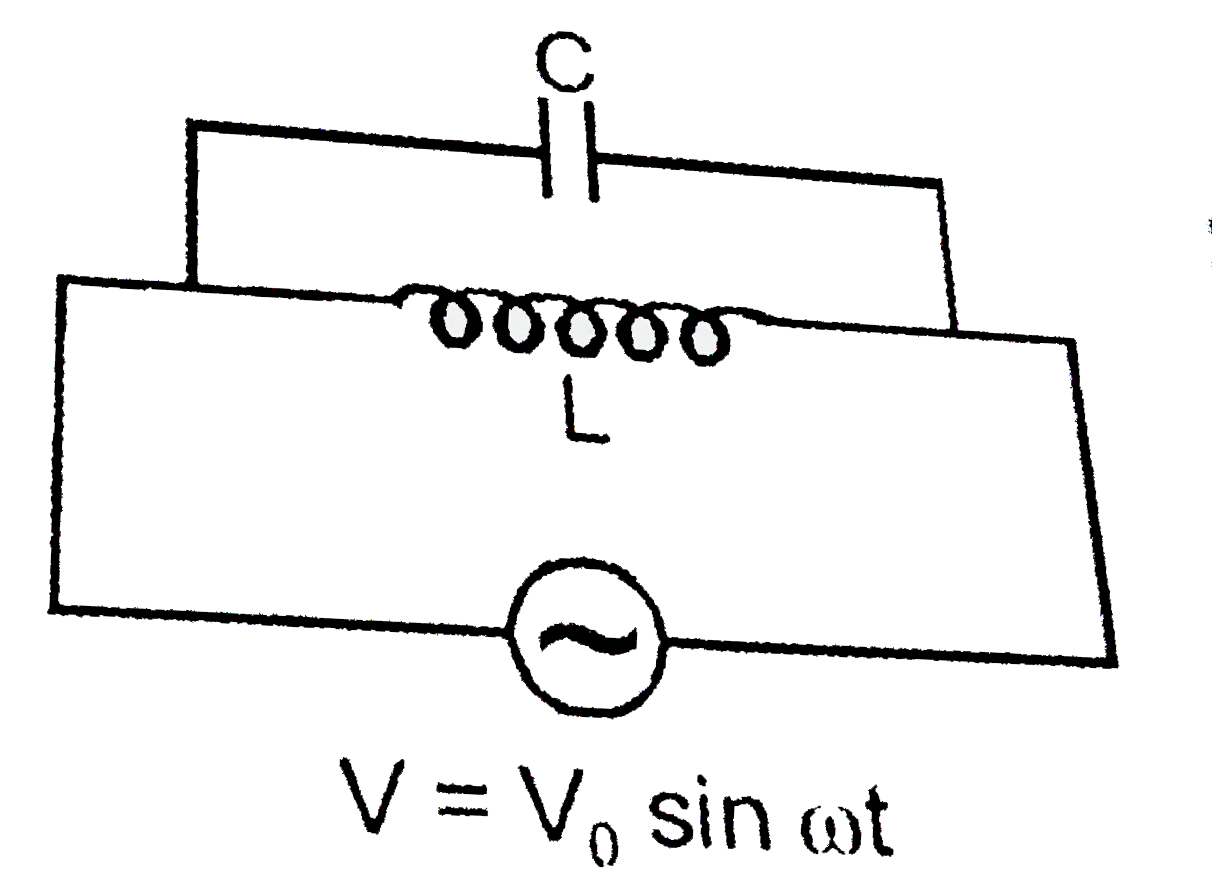
View SolutionFor the circuit shown in the fig., the current through the inductor is 0.9 A while the current through the condenser is 0.4 A. Then
View Solution

