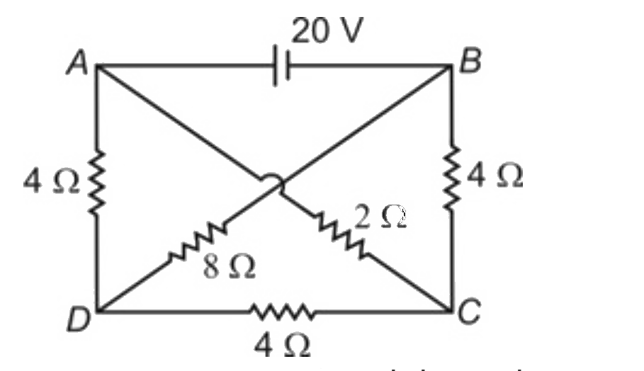
For the circuit shown in figure, which of the below options given is/are correct:
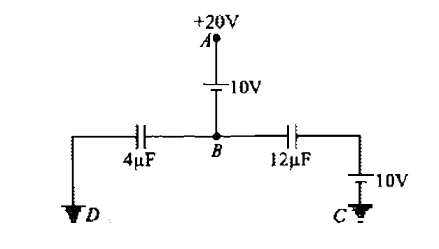
The charge on the 12μF capacitor is zero
The charge on the 12μF capacitor is 30μC
The charge on thhe 4μF capacitor is 30μC
None of these
The correct Answer is:A
Step by step video, text & image solution for For the circuit shown in figure, which of the below options given is/are correct: by Physics experts to help you in doubts & scoring excellent marks in Class 12 exams.
Updated on:21/07/2023Topper's Solved these Questions
- CAPACITANCEBook:PHYSICS GALAXY - ASHISH ARORAChapter:CAPACITANCEExercise:ADVANCE MCQS
Explore 26 Videos
- CAPACITANCEBook:PHYSICS GALAXY - ASHISH ARORAChapter:CAPACITANCEExercise:UNSOLVED NUMERICAL PROBLEMS
Explore 40 Videos
- CAPACITANCEBook:PHYSICS GALAXY - ASHISH ARORAChapter:CAPACITANCEExercise:CONCEPTUAL MCQA
Explore 32 Videos
- ATOMIC PHYSICSBook:PHYSICS GALAXY - ASHISH ARORAChapter:ATOMIC PHYSICSExercise:Unsolved Numerical Problems
Explore 39 Videos
- CURRENT ELECTRICITYBook:PHYSICS GALAXY - ASHISH ARORAChapter:CURRENT ELECTRICITYExercise:All Questions
Explore 389 Videos
Similar Questions
Knowledge Check
In the circuit shown in figure, which of the following is correct?
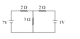 AThe power supplied by 7V cell is 0WBThe power supplied by 1V cell is 1WCThe power absorbed by 1V cell is 1WDThe power absorbed by 7V cell is 14W
For the given circuit shown in figure which of the following statements is/are correct
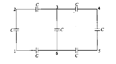 AThe equivalent capacitance between.points 1 and 2 is 15C11BThe equivalent capacitance between poiots 3 and 6 is 5C3CThe equivalent capacitance between points 1 and 3 is 15C14DThe equivalent capacitance between points 3 and 5 is 14C15
In the circuit shown in the figure, which one of following statement is correct
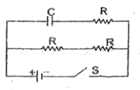 AIf the switch S is closed, the time constant during, charging is RCBif the switch S is closed, the time constant during charging is RC/2.CIf the switch is opened again, the time constant during discharging is 3RCDIf the switch is opened again, the time constant during discharging isRÇ/2
See the electrical circuit shown in this figure. Which of the following equations is a correct equation for it ?
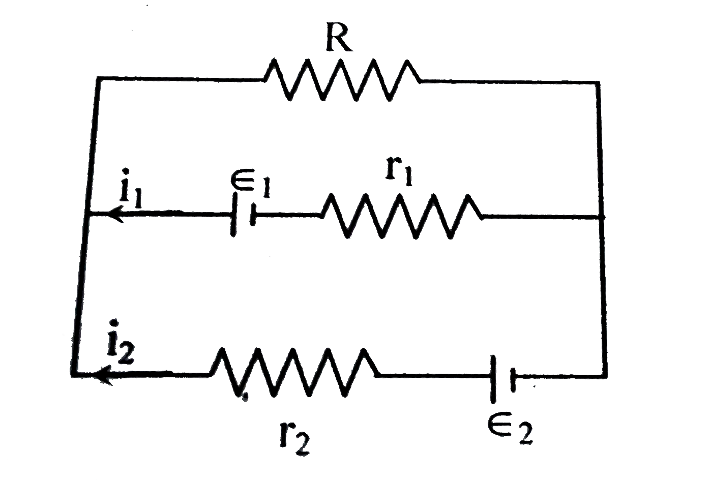
View SolutionFor the given circuit shown in figure below, Time constant is
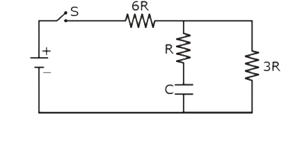
View SolutionThe circuit shown in figure below will act as

View SolutionSee the electrical circuit shown in this figure. Which of the following equations is the correct equation for it ?
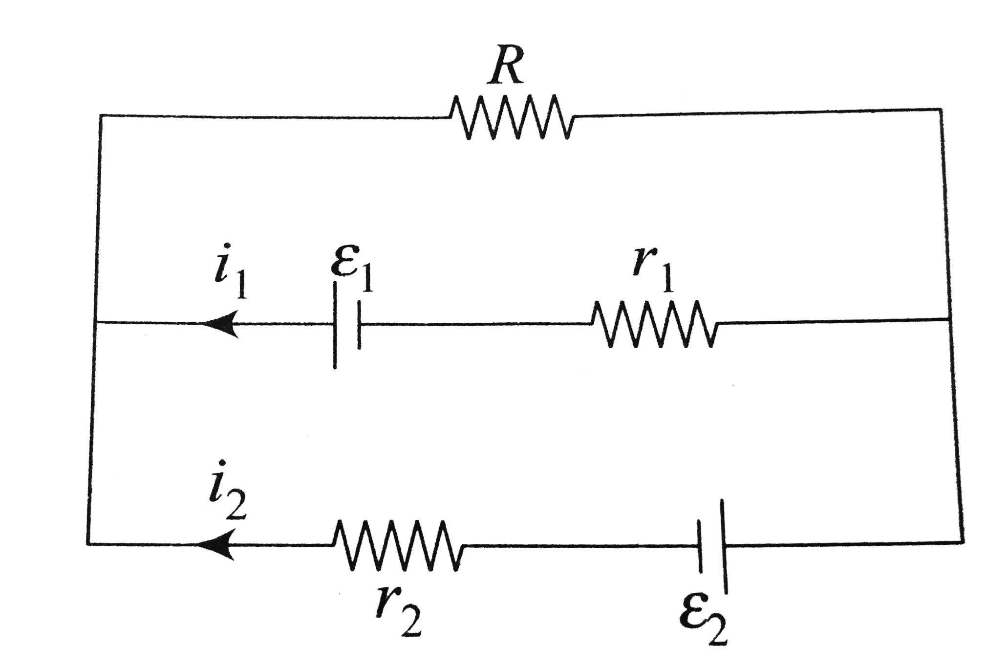
View SolutionIn the circuit shown in fig. mark the correct options.
View Solution


