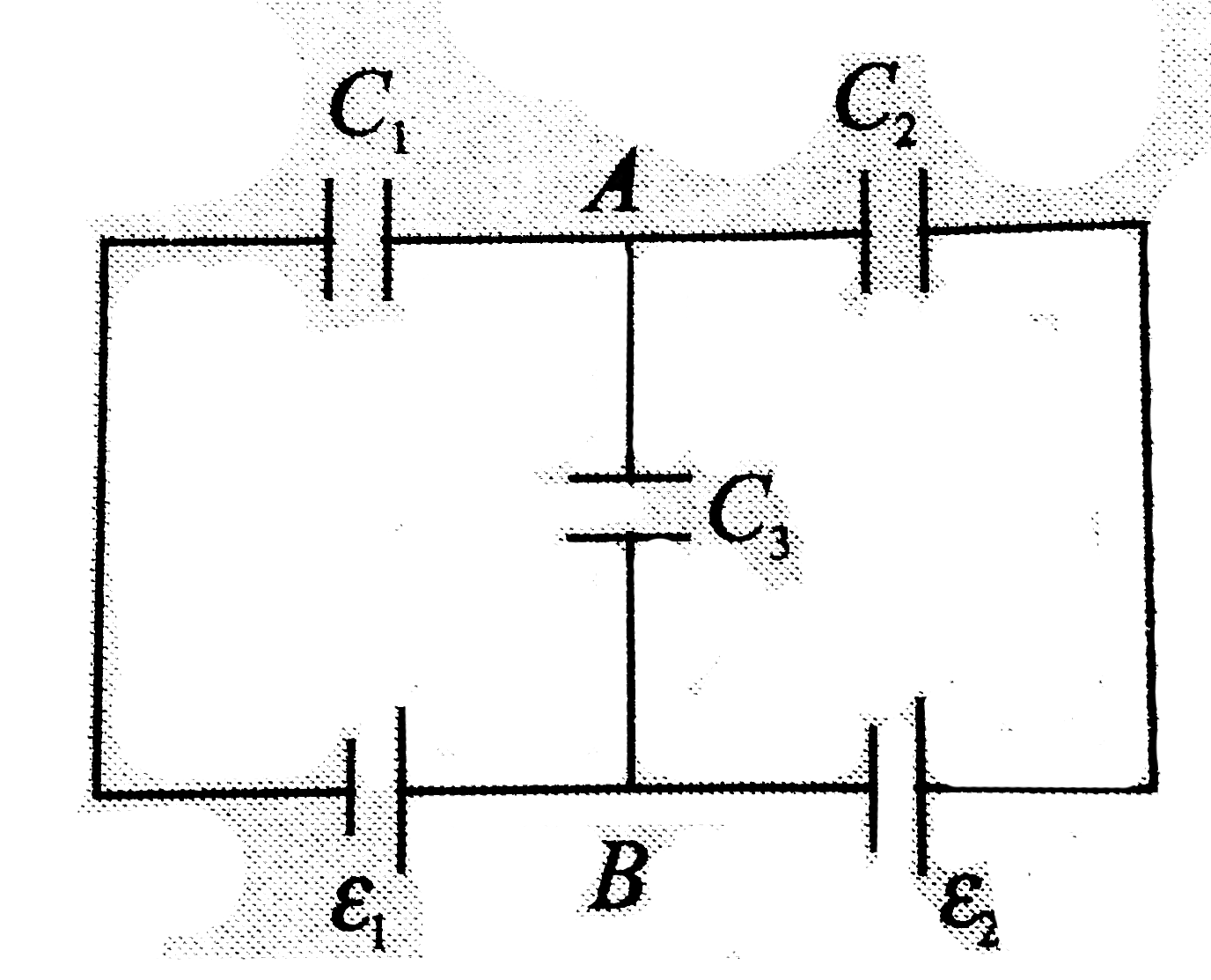
In the circuit shown in figure four capacitors are connected to a battery. Determine the potential difference VM−VN between· points M and N of the circuit. Find the conditions under which it is equal to zero.
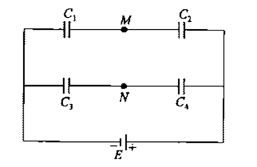
Step by step video & image solution for In the circuit shown in figure four capacitors are connected to a battery. Determine the potential difference V_(M)-V_(N) between· points M and N of the circuit. Find the conditions under which it is equal to zero. by Physics experts to help you in doubts & scoring excellent marks in Class 12 exams.
Updated on:21/07/2023Topper's Solved these Questions
- CAPACITANCEBOOK - PHYSICS GALAXY - ASHISH ARORACHAPTER - CAPACITANCEEXERCISE - DISCUSSION QUESTIONS
22 Videos
- CAPACITANCEBOOK - PHYSICS GALAXY - ASHISH ARORACHAPTER - CAPACITANCEEXERCISE - CONCEPTUAL MCQA
32 Videos
- ATOMIC PHYSICSBOOK - PHYSICS GALAXY - ASHISH ARORACHAPTER - ATOMIC PHYSICSEXERCISE - Unsolved Numerical Problems
39 Videos
- CURRENT ELECTRICITYBOOK - PHYSICS GALAXY - ASHISH ARORACHAPTER - CURRENT ELECTRICITYEXERCISE - All Questions
389 Videos
Similar Questions
Knowledge Check
Four capacitors are connected as shown in figuere to a 30V battery. The potential difference between points a and b
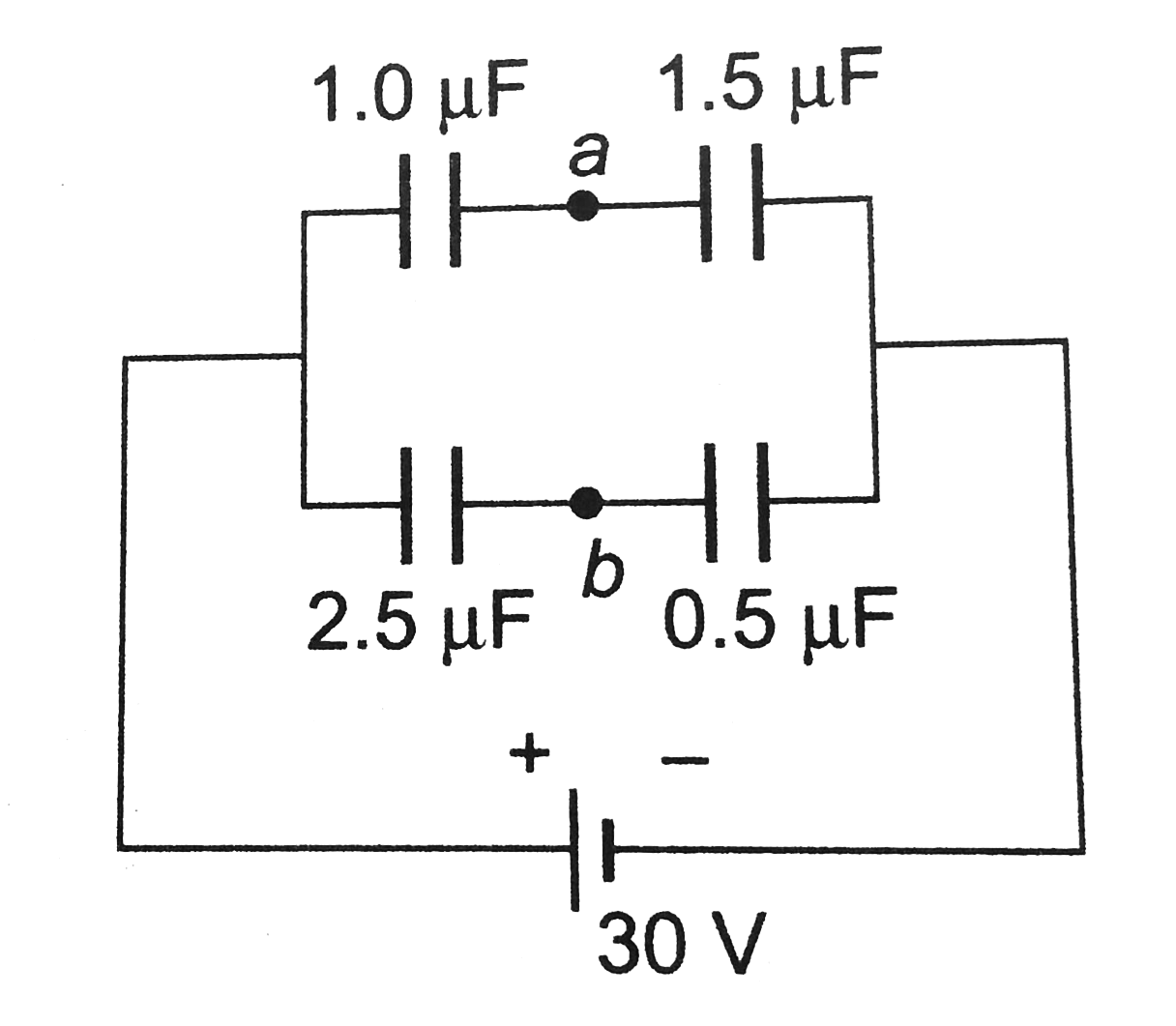 A5VB9VC10VD13V
In the circuit shown in the figure four capacitors are connected to a battery. The p.d across the 7μF capacitor is 6V.
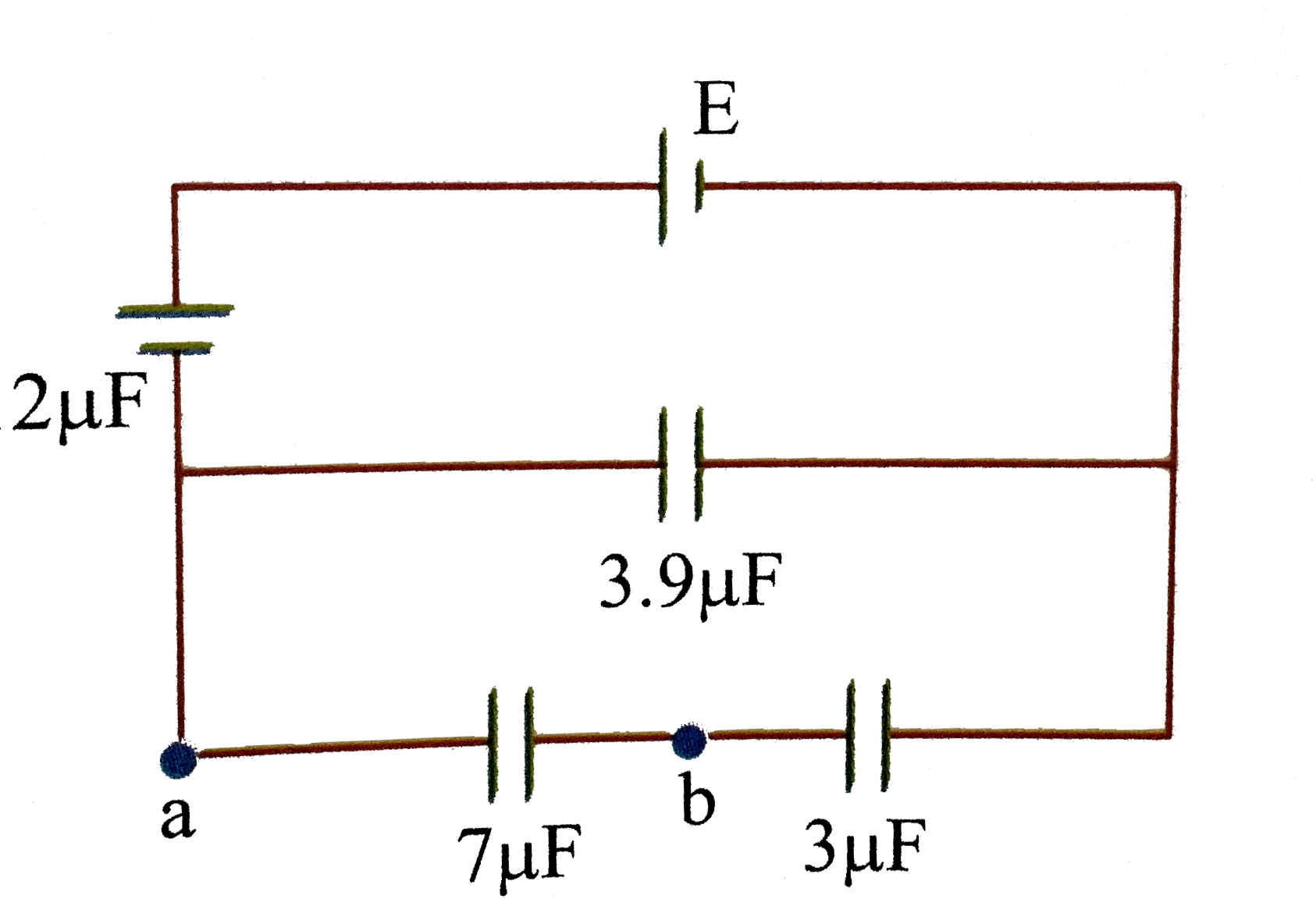 .AThe p.d across the 12μF capacitor is 10VBThe charge on the 3μF capacitor is 42μCCThe p.d across 3.9μF capacitor is 10VDThe emf of the battery is 30V
The potential difference between points A and B in the circuit shown in figure will be
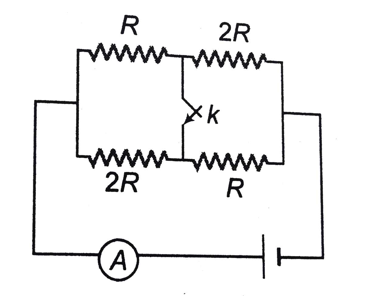 A1VB2VC−3VDnone of these
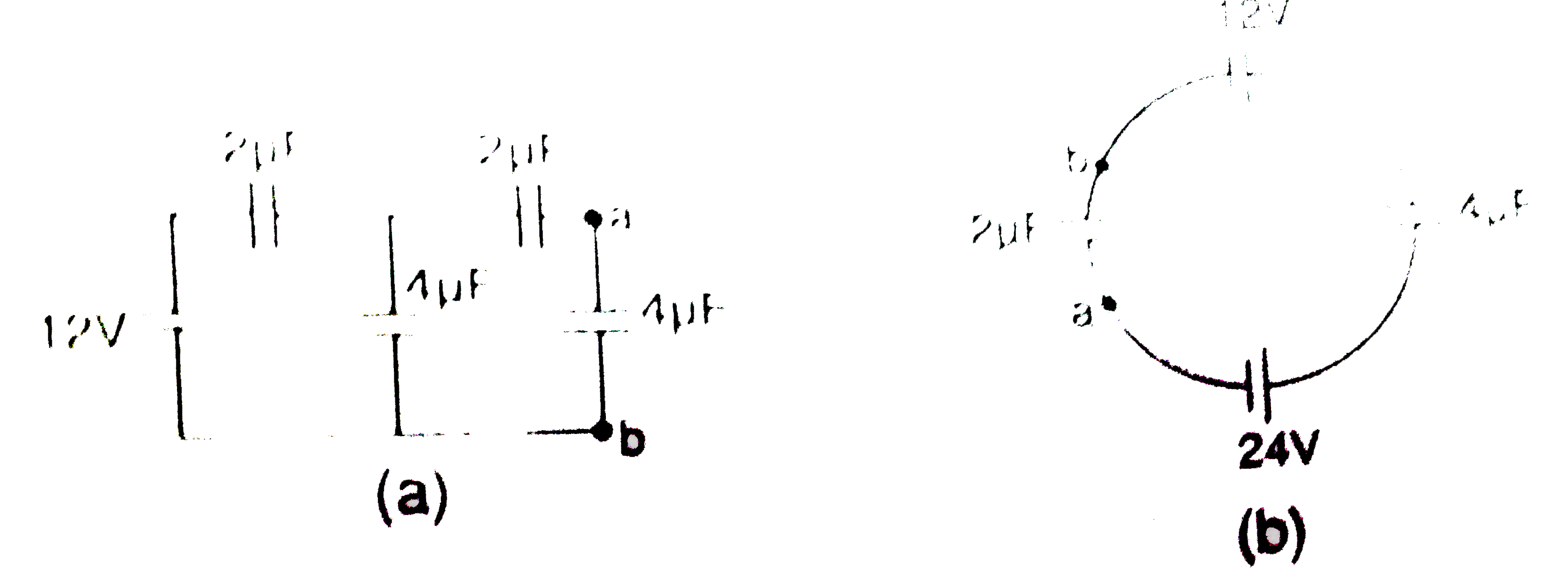
Find the potential difference Va−Vb between the points a and b shown in each part of the figure.
View SolutionThe potential difference (Vp−VQ) between the points P and Q in the part of a circuit as shown in figure is
_PHY_E05_110_Q01.png)
View Solution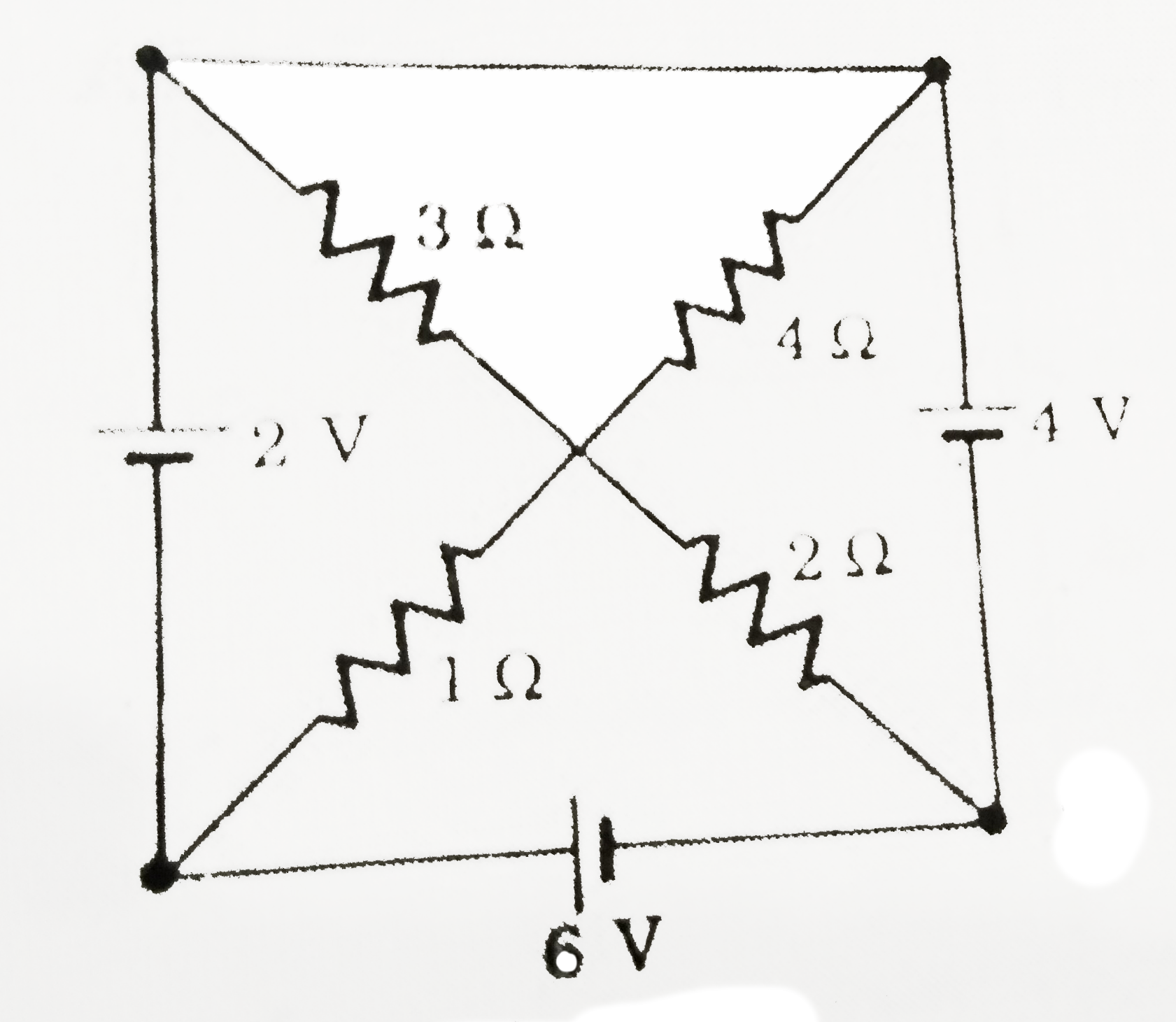
In the network shown in figure. (i) calculate the current of the 6V battery and (ii) determine the potential difference between the points A and B.
View SolutionThe potential difference (VP−VQ) between the points P and Q in the part of a circuit as shown in figure is
_PHY_E05_026_Q01.png)
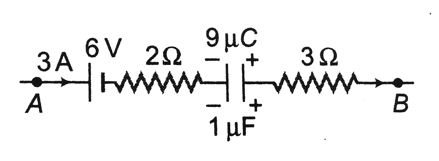
View SolutionThe potential difference VA−VB between points A and B for the circuit segment shown in figure at the given instant is
View Solution

 .
. 