Draw the circuit for experimental verification of Ohm's law using a source of variable DC voltage, a main resistance of 100Ω, two galvanometers and two resistances of value 106Ω and 10−3Ω respectively. Clearly show the positions of the voltmeter and the ammeter.
The correct Answer is:(##BSLPHYSCMIE01229_A01##)
Step by step video, text & image solution for Draw the circuit for experimental verification of Ohm's law using a source of variable DC voltage, a main resistance of 100 Omega, two galvanometers and two resistances of value 10^6 Omega and 10^-3Omega respectively. Clearly show the positions of the voltmeter and the ammeter. by Physics experts to help you in doubts & scoring excellent marks in Class 12 exams.
Updated on:21/07/2023Topper's Solved these Questions
- SEMICONDUCTORSBook:BANSALChapter:SEMICONDUCTORSExercise:Exercise-4 Section-B
Explore 6 Videos
- SEMICONDUCTORSBook:BANSALChapter:SEMICONDUCTORSExercise:CBSE Question
Explore 32 Videos
- SEMICONDUCTORSBook:BANSALChapter:SEMICONDUCTORSExercise:Exercise-3
Explore 24 Videos
- MASTER PRACTICE PROBLEMBook:BANSALChapter:MASTER PRACTICE PROBLEMExercise:Additional topic
Explore 70 Videos
- TEST PAPERSBook:BANSALChapter:TEST PAPERSExercise:PHYSICS PART C
Explore 14 Videos
Similar Questions
Draw the circuit for experimental verfication of Ohm's law using a source of variable DC voltage, a main resistance of 100(Ω), two galvanometers and two resistances of values 106Ω and 10−3 respectively. Clearly show the positions of the voltmeter and the ammeter.
View SolutionDraw the circuit diagram to verify Ohm's Law with the help of a main resistance of 100Ω and tow galvanometer of resistance 106Ωand10−3Ω and a source of varying emf.
Show the correct positions of volmeter and ammeter.
View Solution
Knowledge Check
The equivalent resistances of a series combination of two resistances is XΩ. If the resistances are of 10Ωand40Ω respectively. The value of X will be:
A10ΩB20ΩC50ΩD40ΩA voltmeter of range 0−10V and resistance 200Ωcannot be used as an ammeter, whose range is
A0−500mAB0−250mAC0−100mAD0−25mAAn experiment is performed to calculate the value of an unknown resistance R of range K Ω by using a battery of variable potential difference, a voltmeter of resistance 106Ω and an ammeter of resistance 10−3Ω. Choose the circuit diagram which indicates correctly the position of ammeter and voltmeter so that percentage error in calculation of R is minimum
A B
B C
C Dnone of the above
How will you join the resistors of resistances 3Ω,6Ω and 8Ω to get an equivalent resistance of 10Ω?
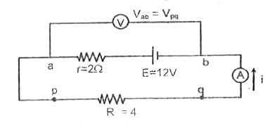
View SolutionThe figure shows a source (a battery) with an emf E of 12 V with an internal resistance r of 2Ω and an external resistance of 4Ω is added to complete the circuit. What are the voltmeter and ammeter readings

View SolutionIn an ammeter, 10% of the main current is passing through galvanometer, it the galvanometer is shunted with a 10 Ω resistance. What is the resistance of the galvanometer ?
View SolutionWhat is the value of shunt resistance required to convert a galvanometer of resistance 100Ω into an ammeter of range 1A ? (Given : Full scale deflection of the galvanometer is 5 mA.)
View SolutionA galvanometer of resistance 100 Ω is converted to a voltmeter of range 10 y by connecting a resistance of 10 Ω. The resistance required to convert the same galvanometer to an ammeter of range 1 A is
View Solution

