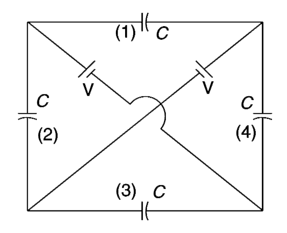
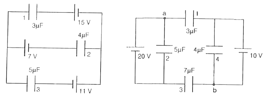
In the circuit shown in the Figure, find the ratio of potential difference across capacitor 1 and 2. The capacitance values are as indicated in the Figure.
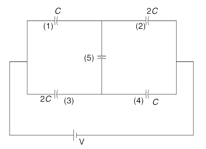
The correct Answer is:
Step by step video, text & image solution for In the circuit shown in the Figure, find the ratio of potential difference across capacitor 1 and 2. The capacitance values are as indicated in the Figure. by Physics experts to help you in doubts & scoring excellent marks in Class 12 exams.
Updated on:21/07/2023Topper's Solved these Questions
Similar Questions
Knowledge Check
In the circuit shown in the figure, the potential difference across the 4.5μF capacitor is
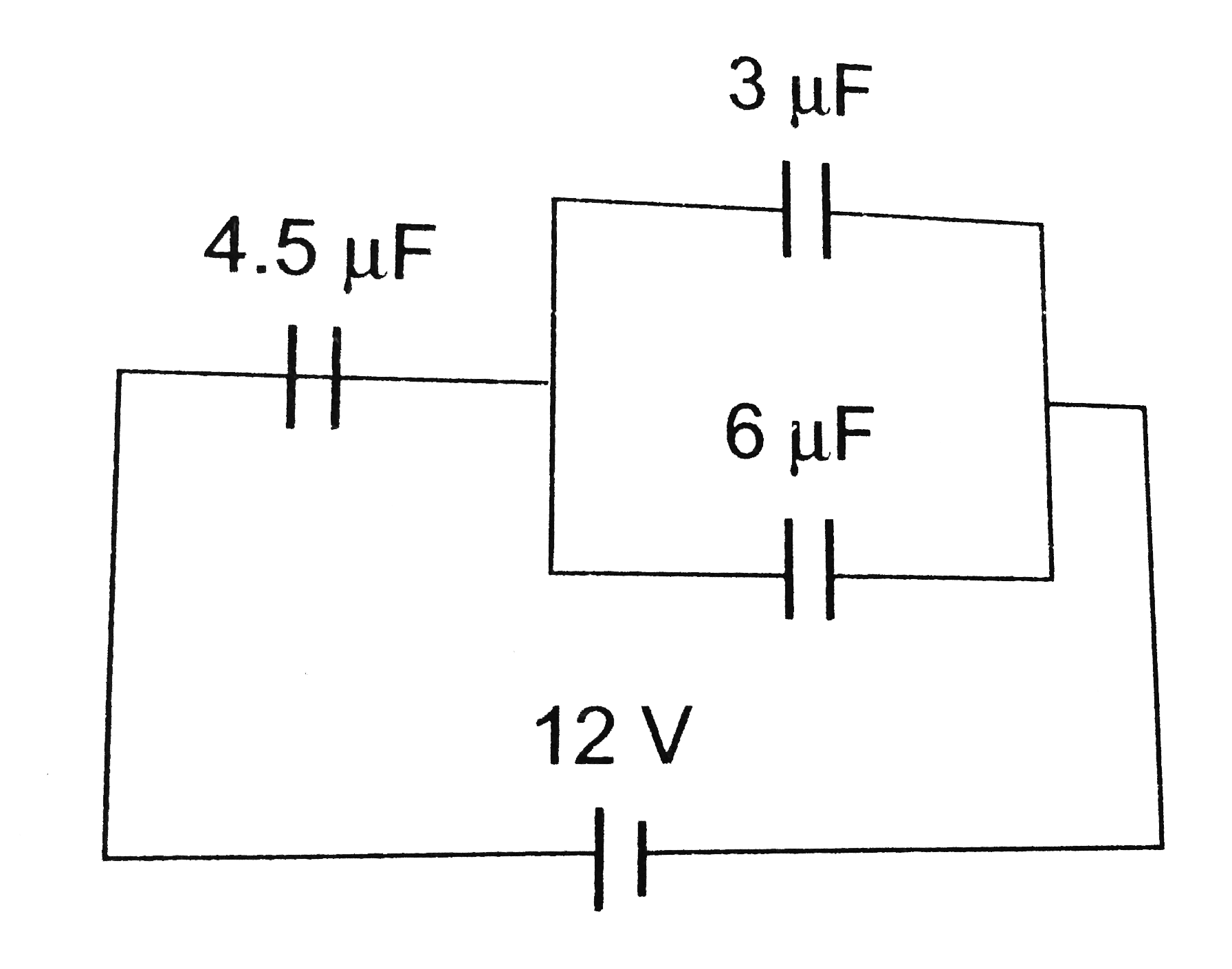 A83voltsB4 voltsC6 voltsD8 volts
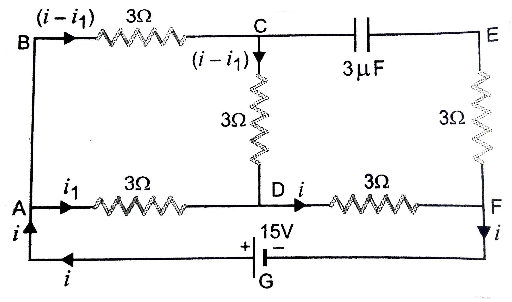
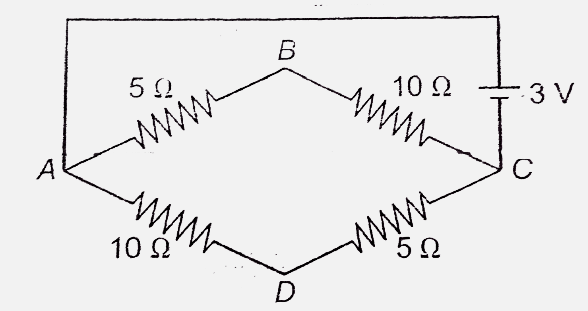
In the network shown in given figure, find the potential difference across BD
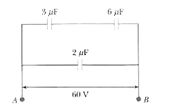
View SolutionIn a ircuit shown in figure, the potential difference across the capacitor of 2μF is
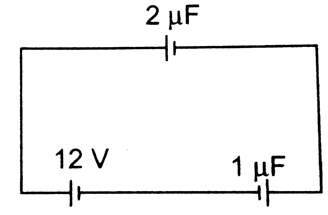
View SolutionIn the circuit shown in the figure, find charge on each capacitor.
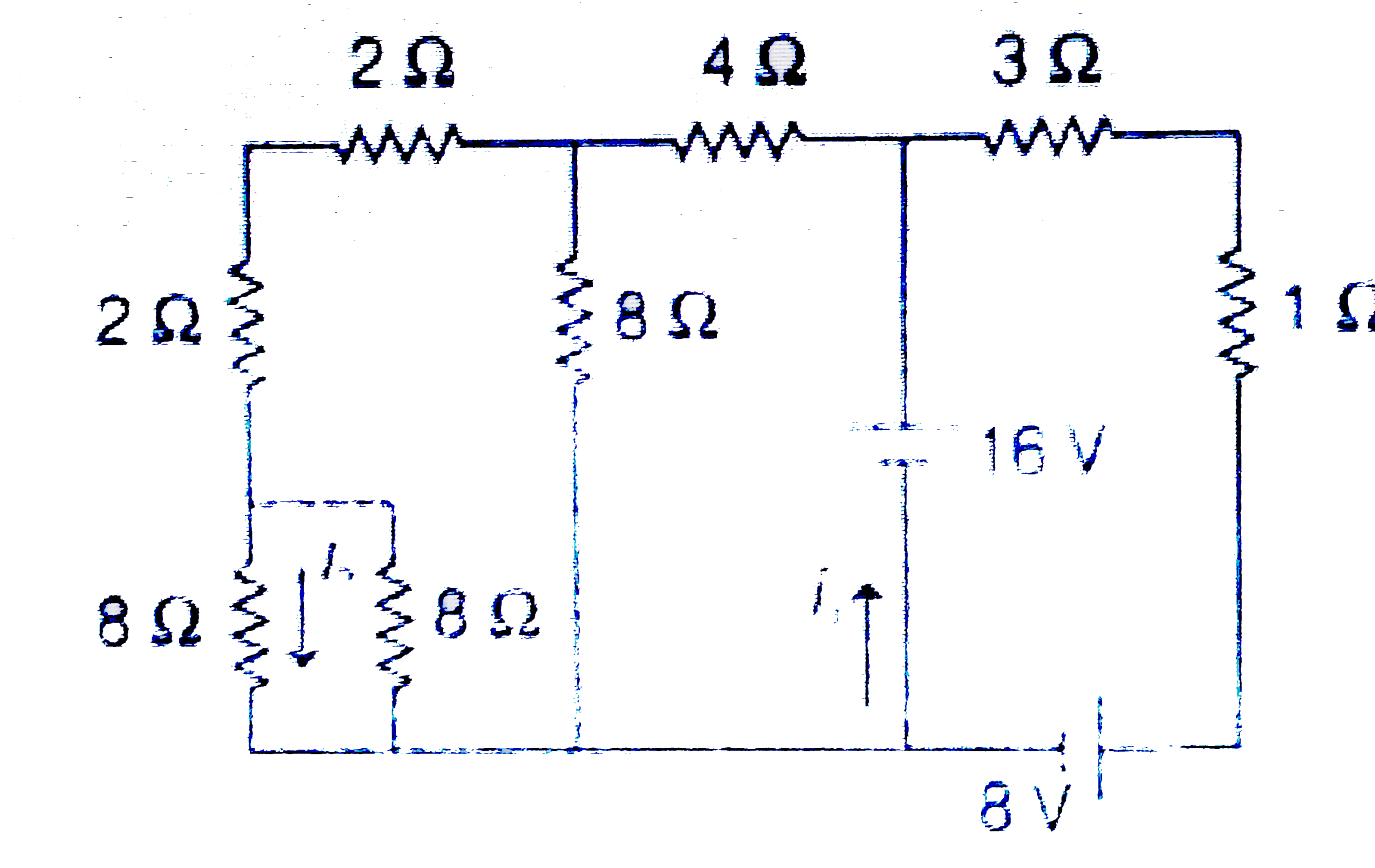
View SolutionIn the circuit shown in figure ,find the ratio of currents i1/i2.
View SolutionIn the following circuit (figure 6.22) find the potential difference across the capacitors 1, 2, and 3.
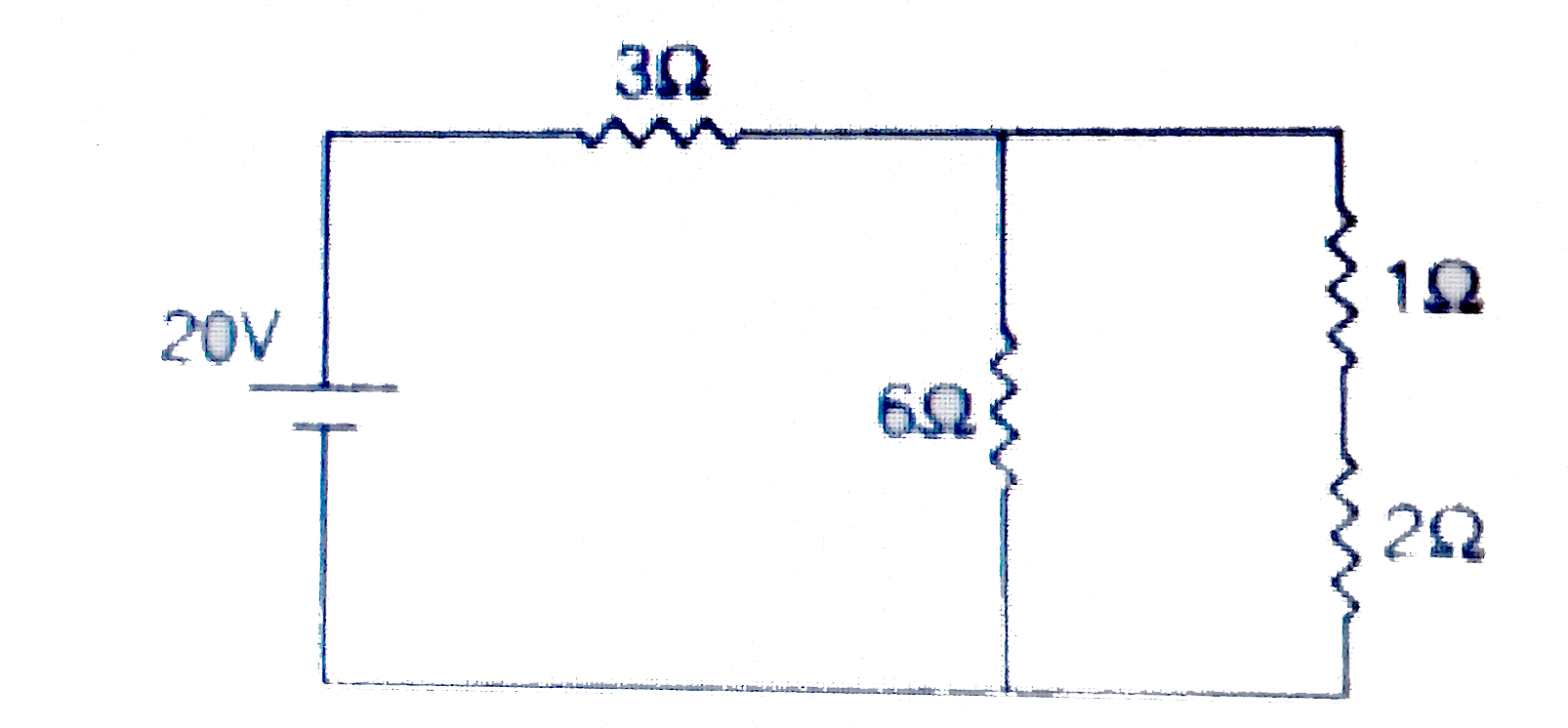
View SolutionIn the circuit shown in figure potential difference across
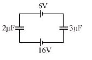
View SolutionWhat is the potential difference across 2μF capacitor in the circuit shown?
View Solution

