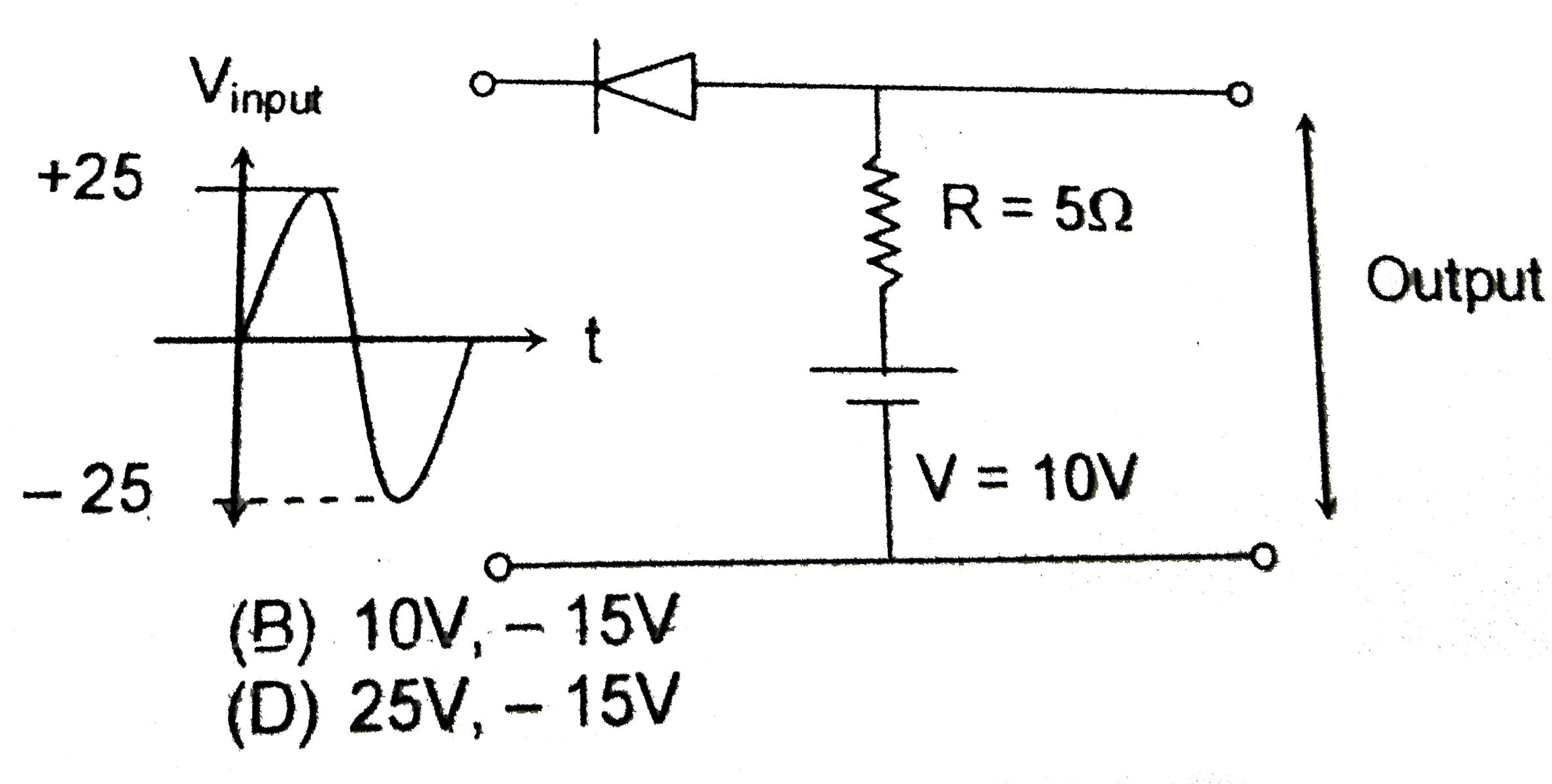
An ideal diode is connected in a circuit with resistance R=5Ω and V=10 volt as shown in figure maximum and minimum value of output voltage. When no load applied is (assume diode to be ideal)
10V, -25 V
10V, -15 V
25V,-25V
25V, -15V
The correct Answer is:A
Positive half cycle
Voutput=10V
For negative half cycle.
Potential difference across output =−25V
Topper's Solved these Questions
- TEST PAPERSBOOK - FIITJEECHAPTER - TEST PAPERSEXERCISE - PHYSICS
747 Videos
- SIMPLE HARMONIC MOTIONBOOK - FIITJEECHAPTER - SIMPLE HARMONIC MOTIONEXERCISE - Assignment Problems (Objective) (Level-II)
20 Videos
- WORK, ENERGY AND POWER BOOK - FIITJEECHAPTER - WORK, ENERGY AND POWER EXERCISE - COMPREHENSIONS ( Comprehension-II)
5 Videos
Similar Questions
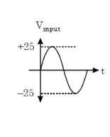
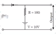
An ideal diode is connected in a circuit with resistance R=50ΩandV=10V. If an AC input signal shown in the figure is given to the circuit, then the maximum and minimum value of output voltage (without load) is
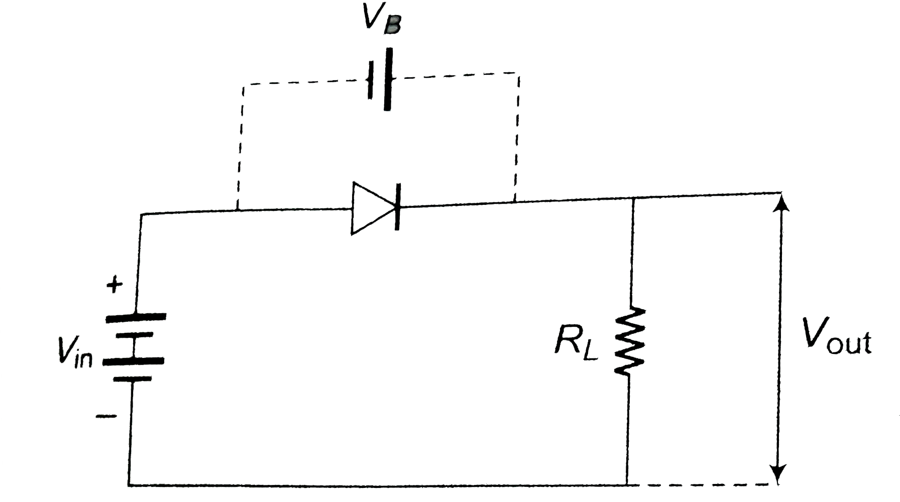
View SolutionA silicon diode is connected to a load resistance RL as shown in the figure. If V∈=15V and RL=10kΩ
(a) If barrier voltage, VB=0.7V then calculate
(i) output voltage across RL
(ii) current in diode and ltbRgt (iii) forward resistance.
(b) If diode is assumed ideal, then what will be
(i) output voltage and
(ii) output current in diode?
View Solution
Knowledge Check
4 ideal diodes are connected as shown in the circuit the current through 50Ω is.
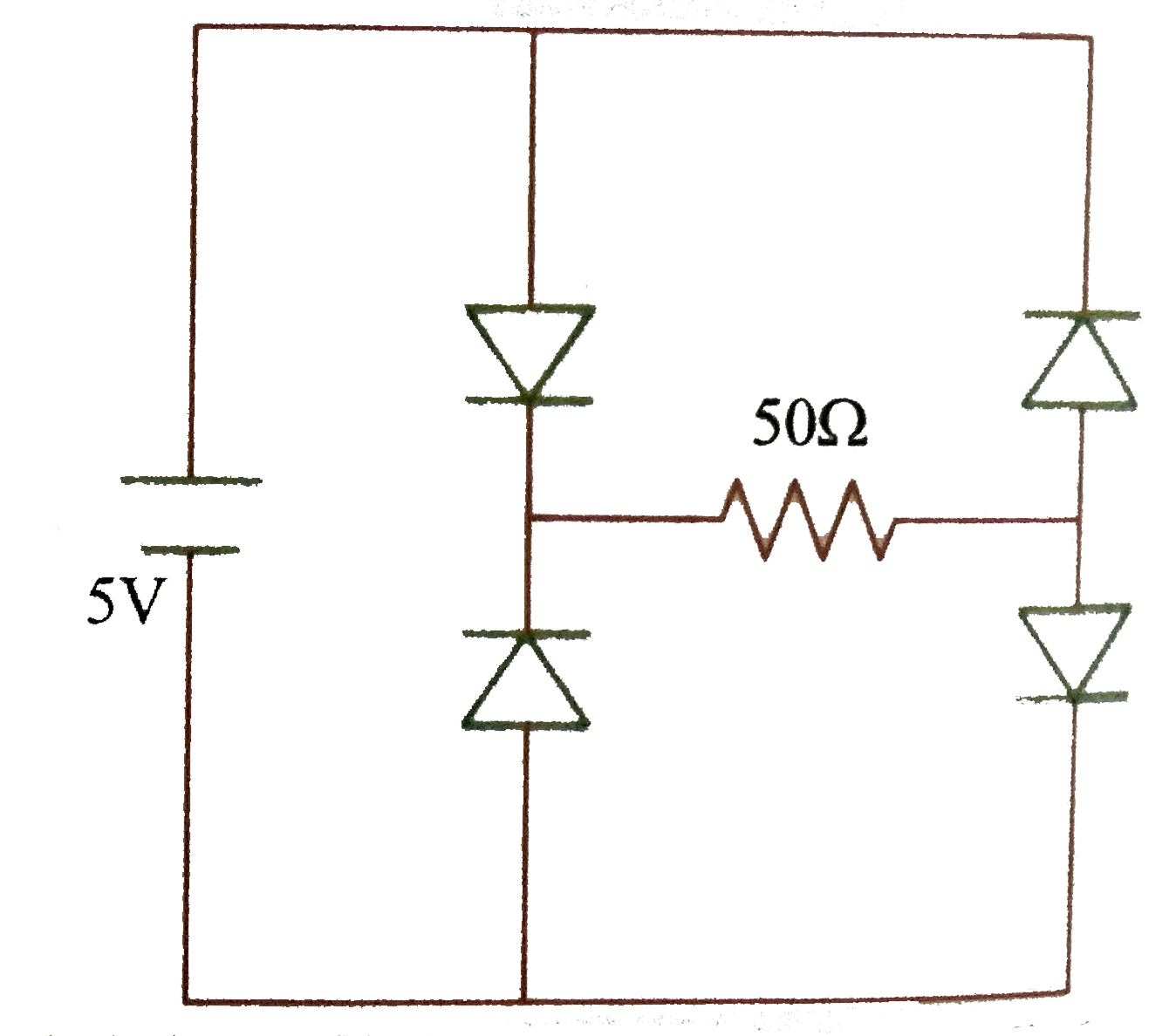 .A0.1AB0.5AC0.6AD1A
A full wave rectifier circuit along with the input and output voltages is shown in the figure
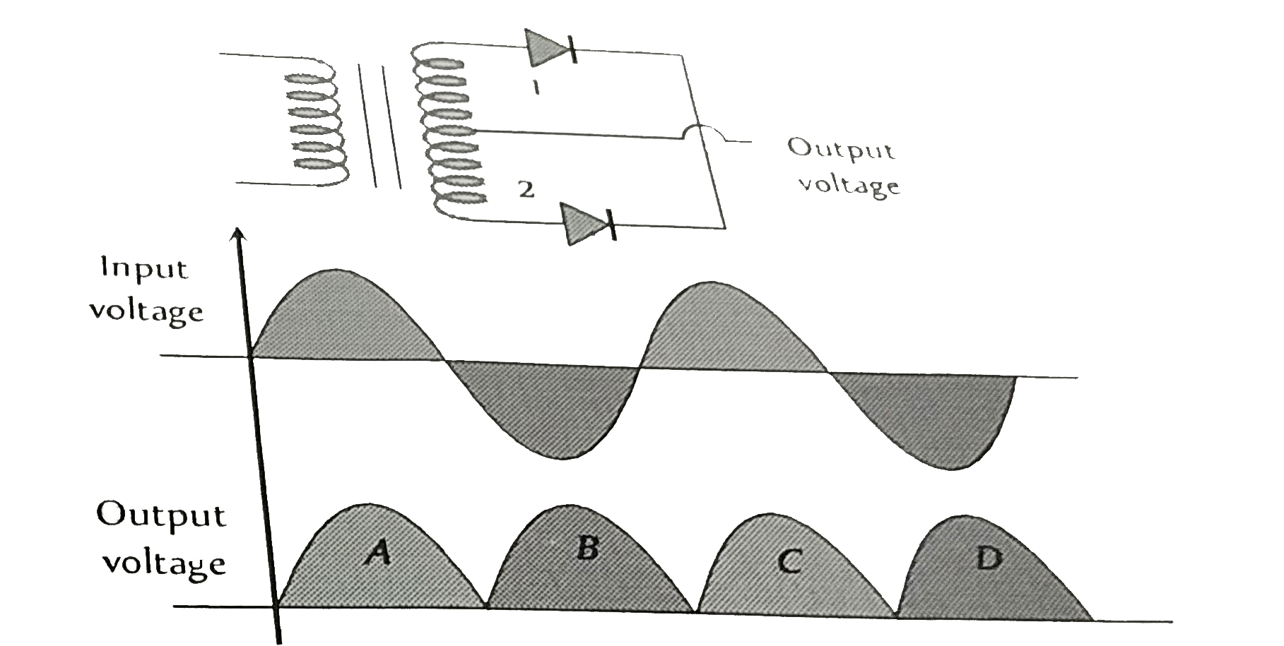
The contribution to output voltage from diode – 2 isAA,CBB,DCB,CDA,DTwo ideal diodes D1 and D2 are connected with the battery of 5 volt as shown in figure. Then the current through diode D1 is
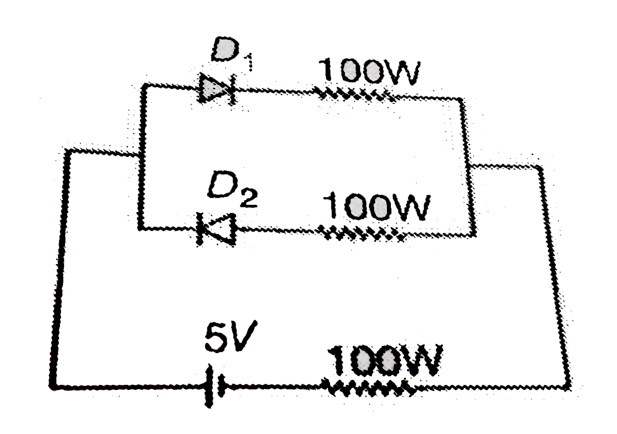 A12.5 mAB25 mACzeroD50 mA
What is an ideal diode ? Draw the output waveform across the load resistor R, If the wavelength is as shown in the figure.
_S01_097_Q01.png)
View SolutionA p-n junction diode in forward bias is connected to a battery of 4 V and a resistance of 80 ω as shown in the ajoining determine the maximum current in the circuit barrier potential of p-n diode is 0.2 V

View SolutionThe 6 V Zener diode shown in the figure has negligible resistance and a knee current of 5 mA. The minimum value of R (in Ω) so that the voltage across it does not fall below 6 V is
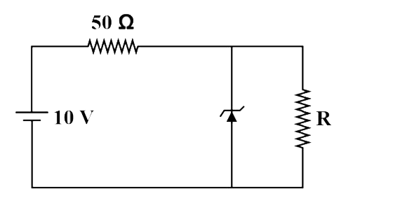
View SolutionThe 6 V Zener diode shown in the figure has negligible resistance and a knee current of 5 mA. The minimum value of R (in Ω) so that the voltage across it does not fall below 6 V is

View SolutionA zener-regulated power supply consists of a 9 V battery connected in series with a resistance of 100Ω and a zener diode. The zener diode maintains a constant voltage drop of 4 V across a load resistance of 400Ω. The current drawn by the load resistance will be
View Solution
