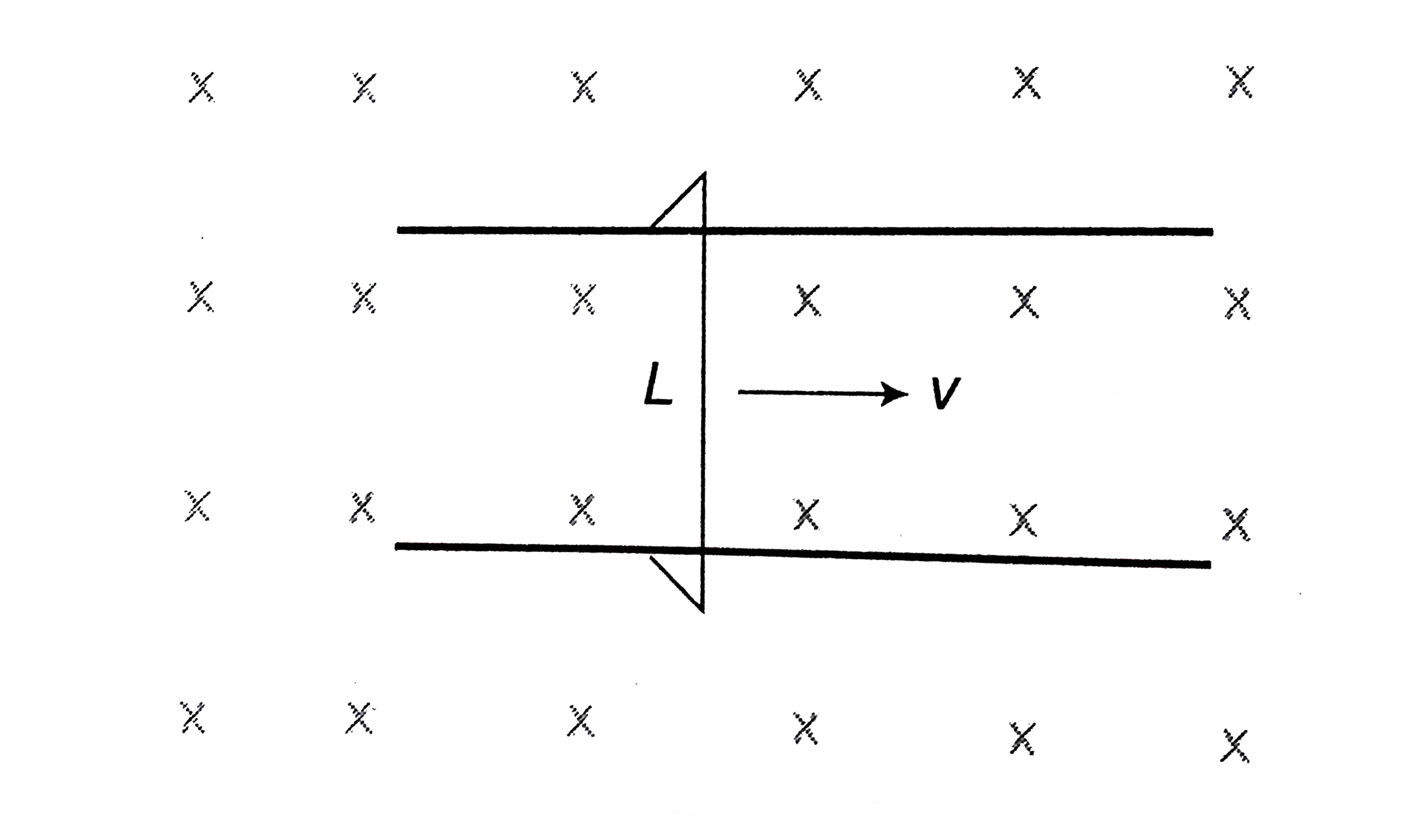
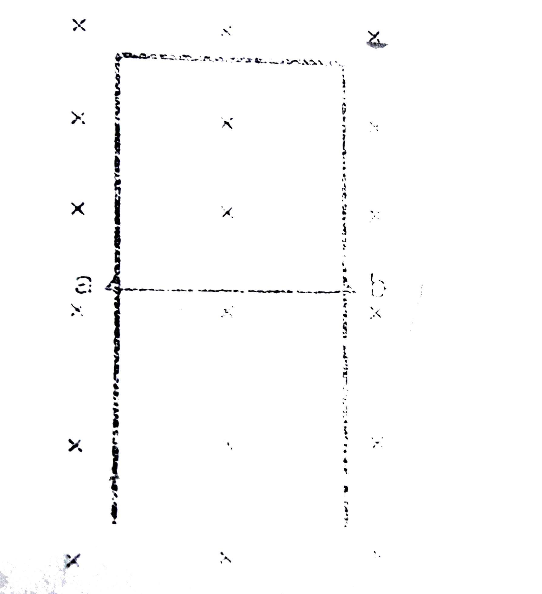
Figure shows a wire sliding on two parallel, conducting rails placed at a separation L . A magnetic field B exists in a direction perpendicular to the plane of the rails. What force is necessary to keep the wire moving at a constant velocity V ?
BvL
Bv2L
zero
B2v2L/R
The correct Answer is:C
Since no current, F=Bil=0
Topper's Solved these Questions
Similar Questions
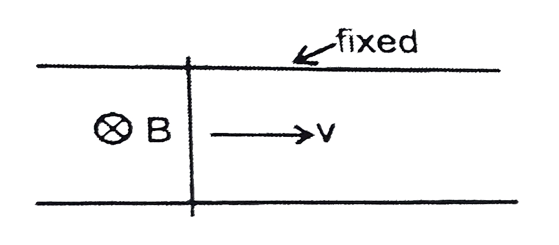
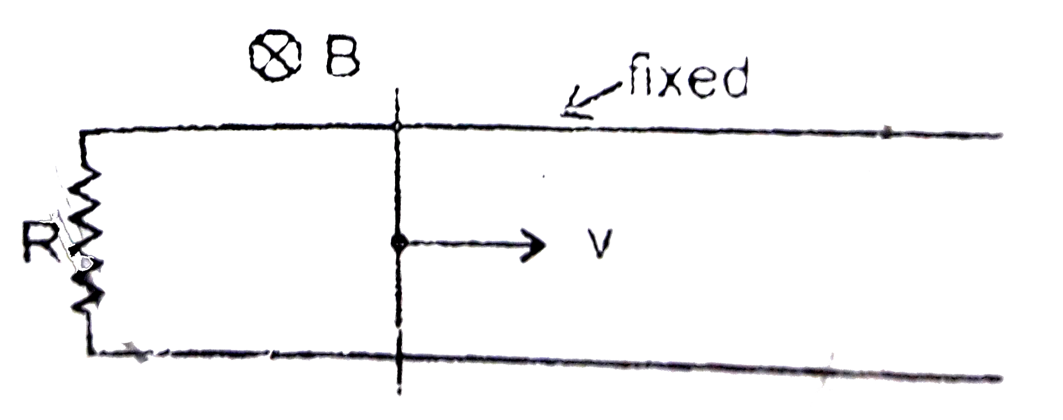
Figure shows a wire of resistance R sliding on two parallel, conducting fixed thick rails placed at a separation l. A magnetic fild B exist in a direction perpendicular to the plane of the rails. The wire is moving with a constant velocity v. Find current through the wire
View SolutionA wire is sliding on two parallel conducting rails placed at a separation of 1m as shown in the figure."Magnetic field of 2T exists in a directịon perpendicular to the rails. The necessary force required to keep the wire moving with a constant velocity of 1cms is π×10−4N. Find n.
View Solution
Knowledge Check
A copper wire ab of length l, resistance r and mass m start sliding at t=0 down a smooth, vertical, thick pair of connected conducting rails as shown in figure. A uniform magnetic field B exists in the space in a direction perpendicular to the plane of the rails which options are correct .
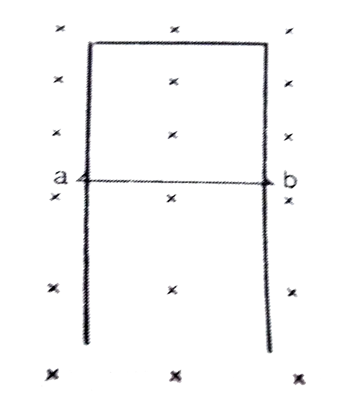 AThe magnitude and direction of the induced current in the wire when speed of the wire v is vBlr, a to bBThe downward acceleration of the wire at this instant g−B2l2mrvCThe velocity of the wire as a function of time vm(1−e−gt/vm),(wherevm=mgrB2l2)DThe displacement of the wire as a function of time vmt−v2mg(1−e−gt/vm),(wherevm=mgrB2l2)
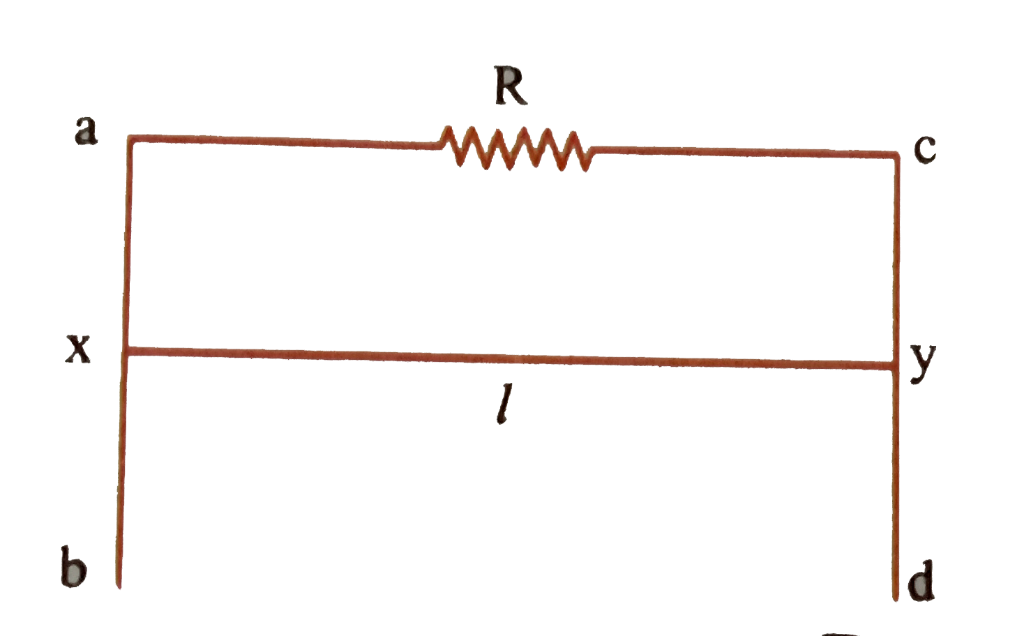
A conducting wire xy of lentgh l and mass m is sliding without friction on vertical conduction rails ab and cd as shown in figure. A uniform magnetic field B exists perpendicular to the plane of the rails, x moves with a constant velocity of
 AmgRBlBmgRBl2CmgRB2l2DmgRB2l
A copper wire ab of length l, resistance r and mass m starts sliding at t=0 down a smooth, vertical, thick pair of connected condcuting rails as shown in figure.A uniform magnetic field B exists in the space in a direction perpendicular to the plane of the rails which options are correct.
 AThe magnitude and direction of the induced current in the wire when speed of the wire v is vBlr, a to bBThe downward acceleration of the wire at this instant g−B2l2mrv.CThe velocity of the wire as a function of time vm(1−e−gt/vm)(where vm=mgrB2l2)DThe displacement of the wire as a function of time vmt−v2mg(1−e−gt/vm)(where vm=mgrB2l2)
A copper wire bent in the shape of a semicircle of radius r translates in its plane with a constant velocity v. A uniform magnetic field B exists in the direction perpendicular to the plane of the wire. Find the emf induced between the ends of the wire if (a) the velocity is perpendicular ot the diameter joining free ends, (b) the velocity is parallel to this diameter.
View SolutionA conducting rod of length l slides at constant velocity v on two parallel conducting rails, placed in a uniform and constant magnetic field B perpendicular to the plane of the rails as shown in Fig.3.49. A resistance R is connected between the two ends of the rails.
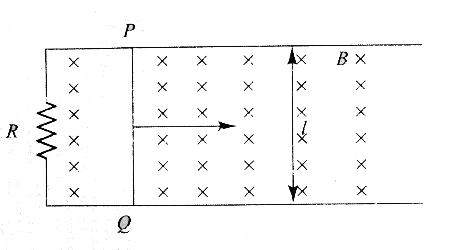
(a) Idenify the cause which produces change in magnetic flux.
(b) Identify the direction of current in the loop.
( c) Determine the emf induced in the loop.
(d) Compute the electric power dissipated in the resistor.
(e) Calcualte the mechenical power required to pull the rod at a cinstant velovity.
View SolutionA resistance R is connected between the two ends of the parallel smooth conducting rails.A conducting rod lies on these fixed horizontal rails and a uniform constant magnetic field B exists perpendicular to the plane of the rails as shown in the figure.If the rod is given a velocity v and released as shown in figure, it will stop after some time, which option are correct:
View Solution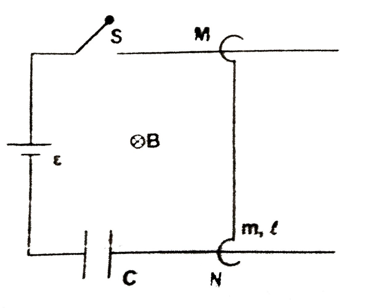
A conducting rod MN of mass m and length 'l' is placed on parallel smooth conducting rails connected to an uncharged capacitor of capacitance C and a battery of emf ε as shown. A uniform magnetic field B is existing perpendicular to the plane of the rails. The steady state velocity acquired by the conducting rod MN after closing switch S is (neglect the resistance of the parallel rails and the conducting rod)
View SolutionA conducting rod of length is moved at constant velocity v0 on two parallel, conducting, smooth, fixed rails, that are placed in a uniform constant magnetic field B perpendicular to the plane for the rails as shown in Fig. A resistance R is connected between the two ends of the rails.
Then which of the following is/are correct:

View Solution

