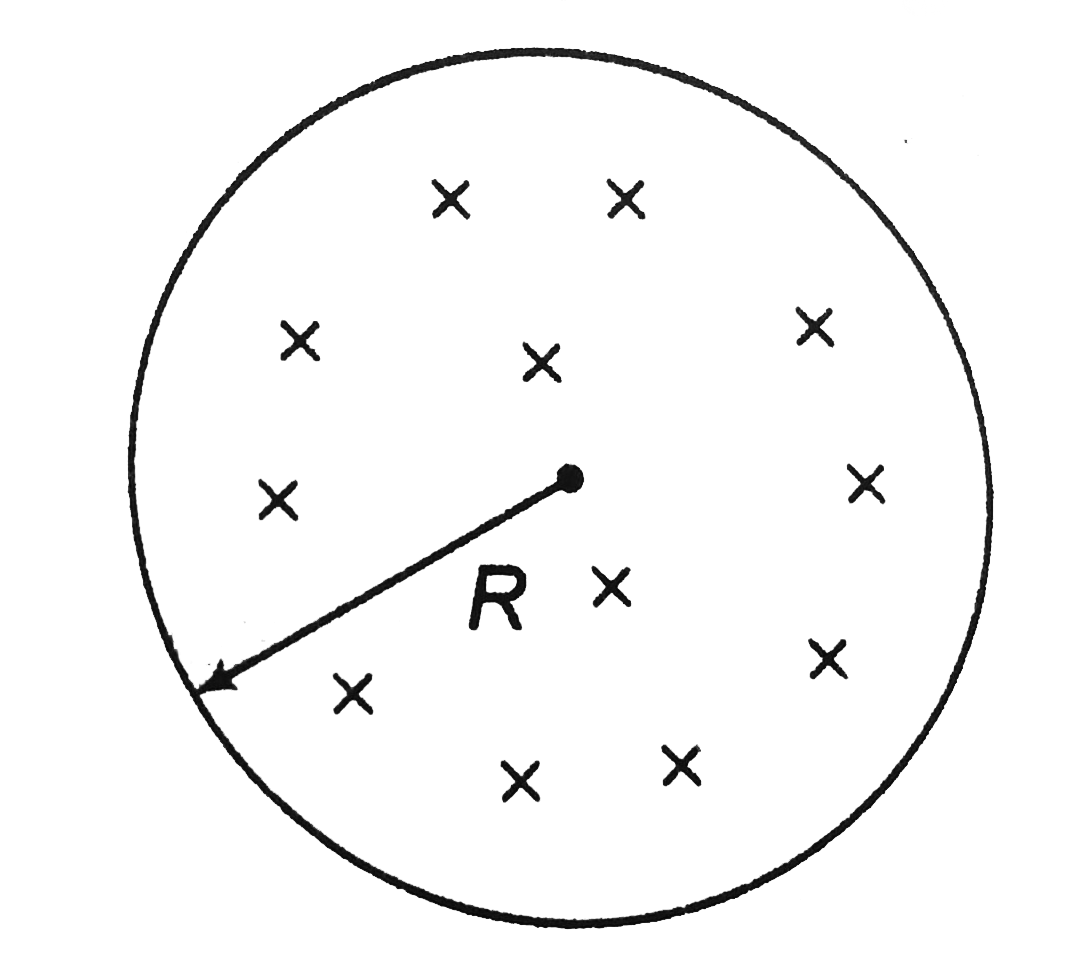
The magnetic field at all points within the cyllindrical region whose cross section is indicated in the accompanying Figure starts increasing at a constant rate α. T/s. find the magnitud of electric field as a function of r, the distance from the geometric centre of the region.
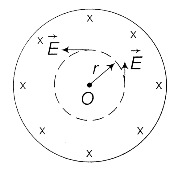
r<R
∮→E.→dt=dϕdt=ddt(B.πr2)
E∮di=dBdt.πr2
E.2πr=α.πr2
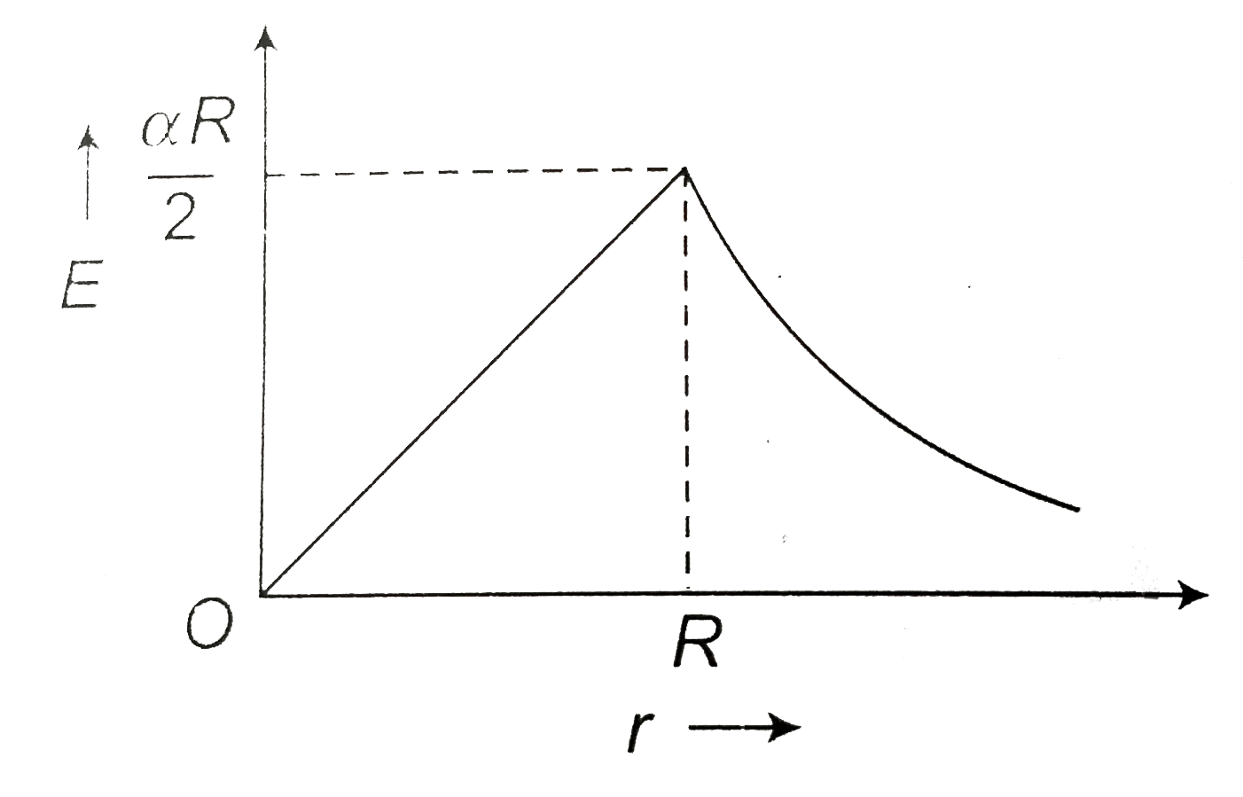
E=αr2(Eαr)
E will be tangential to circle at every point and its direction will be as of inducd current i.e. anticlockwise.
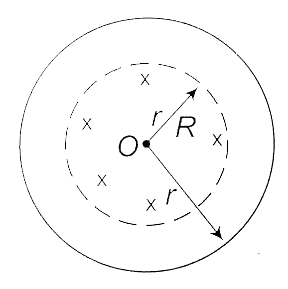
(b) r>R : ∮→E.→dt=dϕdt=ddt(B.πR2)
E∮di=dBdt.πR2
E.2πr=α.πR2
E=αr2(Eα1/r)
r=R , E=αR2
Topper's Solved these Questions
Similar Questions
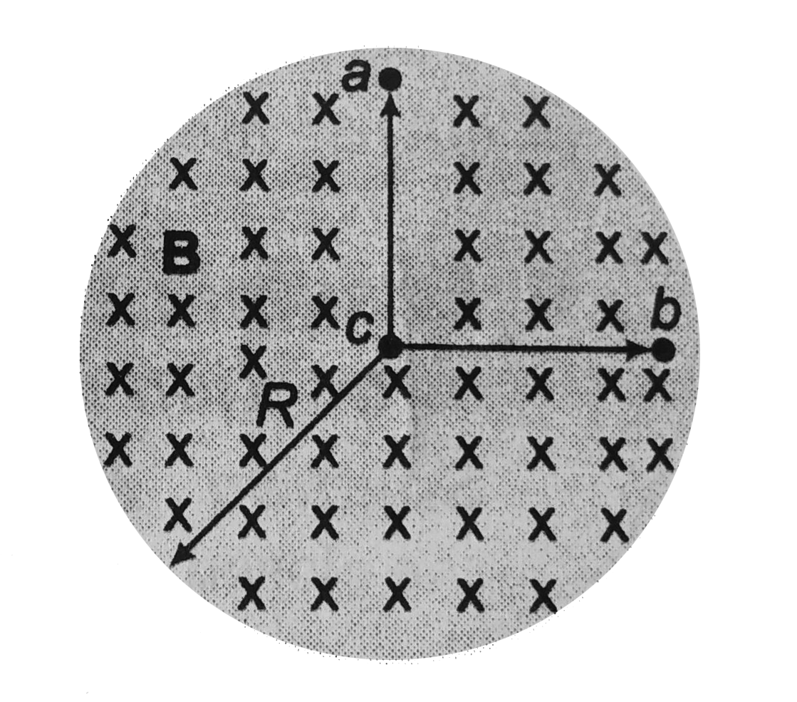
The magnetic field B at all points within a circular region of the radius R is uniform space and directed into the plane of the page in figure. If the magnetic field is increasing at a rate dB/dt what are the magnitude and direction of the force on as stationary positive point charge q located at points a,b,c? (Point a is a distance r above the centre of the region, point b is a distance r to the right to the centre and point c is at the centre of the region).
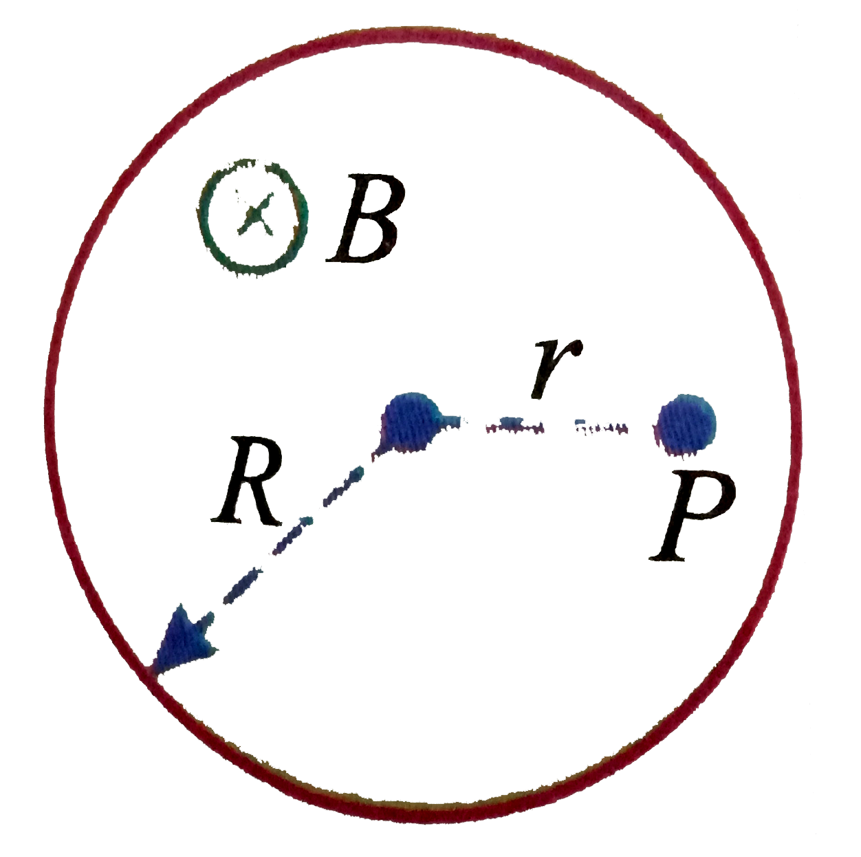
View SolutionA uniform magentic field of induction B is confined in a cyclinderical region of radius R. If the field is incresing at a constant rate of dBdt=αT/s, then the intensity of the electric field induced at point P, distant r from the axis as shown in the figure is proportional to :
View Solution
Knowledge Check
The magnetic field within cylindrical region whose cross - section is indicated starts increasing at a constant rate α tesla/sec . The graph showing the variation of induced field with distance r from the axis of cylinder is :
 A
A B
B C
C D
D
Consider a conducting circular loop placed in a magentic filed as shown. When magnetic field changes with time, magentic flux also changes and emf is induced.
e=−dϕdt
If resistance of loop is R then induced current.
i=eR
For Current, charge must have come into motion. Magnetic force cannot make the statinoary charges to move. Actually there is an induced electric field in the conductor caused by changing magnetic flux, which make the change to move
∫→E.d→l=e=−dϕdt
This induced electric field is non-electrostatic by nature. line integral of →E around a closed path is non-zero

The magnetic field within cylindrical region whose cross - section is indicated starts increasing at a constant rate α tesla/sec The graph showing the variation.of induced electric field with distance r from the axis of cylinder is :A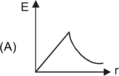 B
B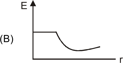 C
C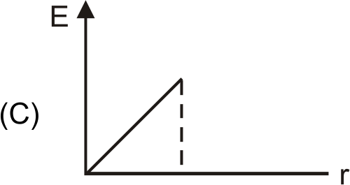 D
D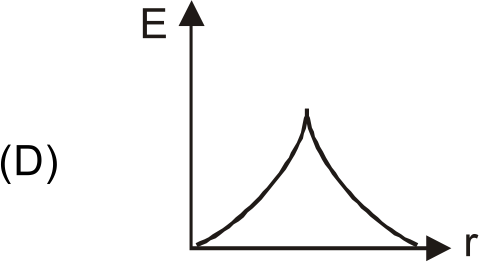
An electruc field of 300V/m is confined to a circular area 10cm in diameter. If the field is increasing at the rate of 20V/m−s, the magnitude of magnetic field at a point 15cm from the centre of the circle will be-
A1.85×10−15TB1.85×10−16TC1.85×10−17TD1.85×10−18T
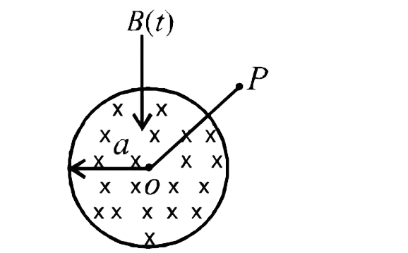
A uniform but time-varying magnetic field B(t) exists in a circular region of radius a and is directed into the plane of the paper, as shown in the figure. The magnitude of the induced electric field at point P at a distance r from the centre of the circular region
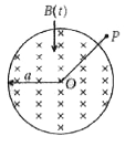
View SolutionA uniform but time-varying magnetic field B (t) exists in a circular region of radius a and is directed into the plane of the paper as shown . The magnitude of the induced electric field at point P at a distance r from the centre of the circular region is
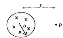
View SolutionA uniform but time-varying magnetic field B(t) exists in a circular region of radius a and is directed into the plane of the paper, as shown. The magnitude of the induced electric field at point P at a distance r from the centre of the circular region
View SolutionA uniform but time varying magnetic field is present in a circular region of radius R. The magnetic field is perpendicular and into the plane of the loop and the magnitude of field is increasing at a constant rate α. There is a straight conducting rod of length 2R placed as shown in figure.
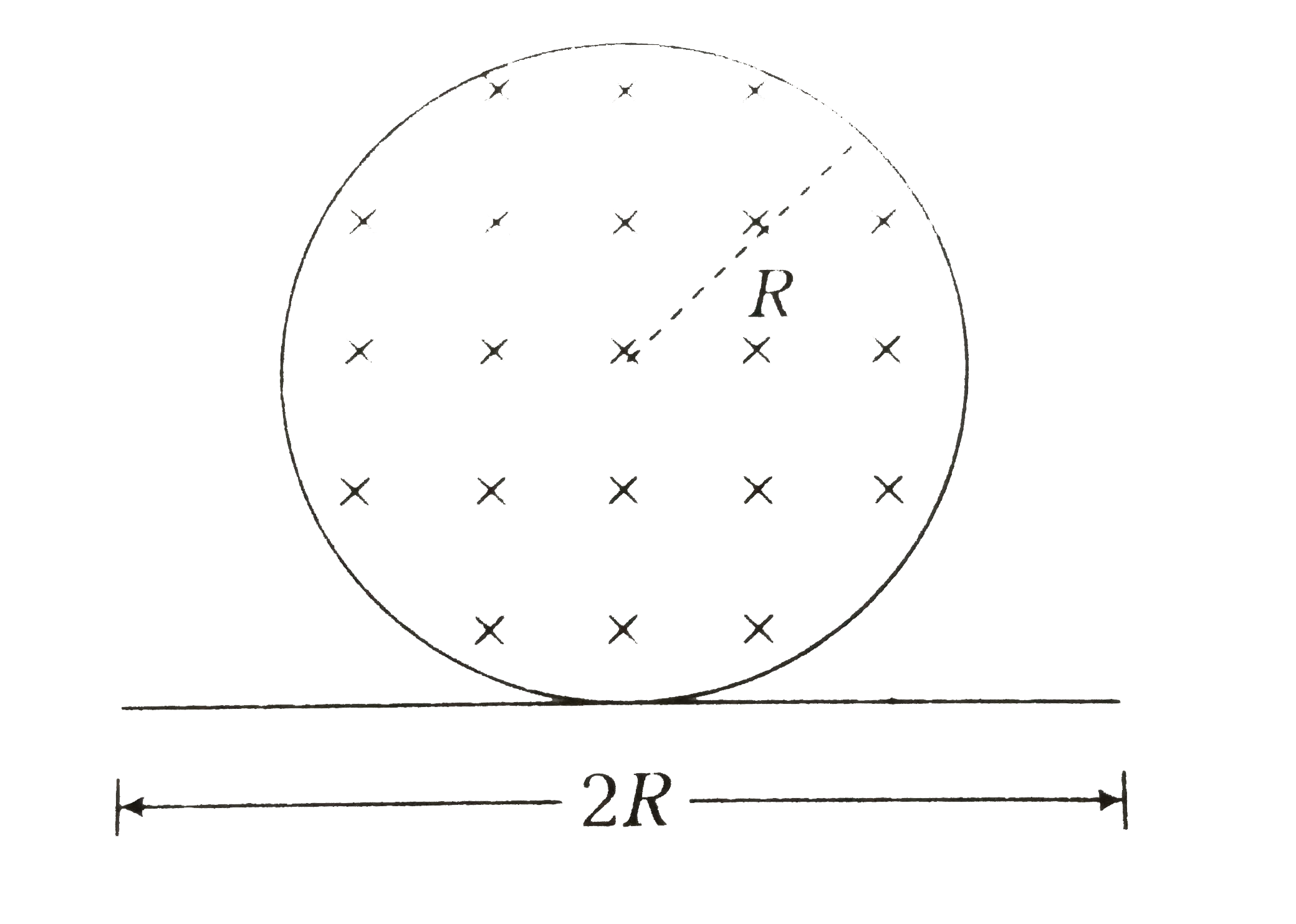
The magnitude of induced emf across the rod is
View SolutionA cylindrical conductor of radius R is carrying constant current. The plot of the magnitude of the magnetic field, B with the distance, d from the centre of the conductor , is correctly represented by the figure:
View Solution
