A bridge circuit is shown in the diagram. A student wrote the following expressions for currents at the points A, B, C and D by using Kirchhoff's first law. Point out the wrong equation.
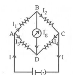
at A,I=I1+I3
at B,I1=I2+Ig
at C,I2=I4+I
at D,I3+Ig=I4
The correct Answer is:D
Step by step video & image solution for A bridge circuit is shown in the diagram. A student wrote the following expressions for currents at the points A, B, C and D by using Kirchhoff's first law. Point out the wrong equation. by Physics experts to help you in doubts & scoring excellent marks in Class 12 exams.
Updated on:21/07/2023Topper's Solved these Questions
Similar Questions
Knowledge Check
For the circuit shown in figure. The point F is grounded. Which of the following is wrong statement ?
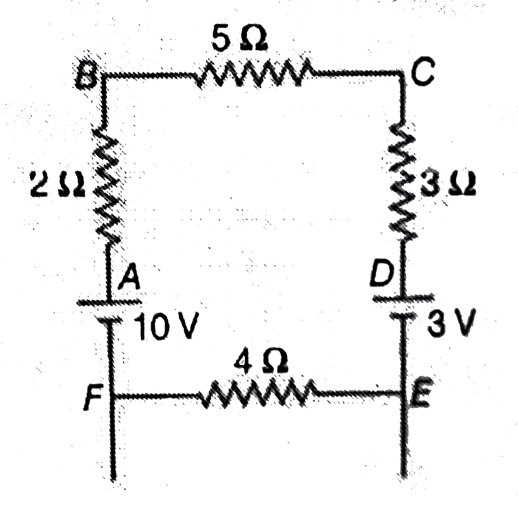 AD is at 5 VBE is at zero potentialCThe current in the circuit will be 0.5 ADNone of the above
In the circuit it shown in the figure, the value of Resistance X, when potential difference between the points B and D is zero will be
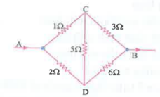 A9ohmB8ohmC6ohmD4ohm
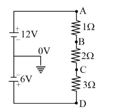
In the circuit diagram shown in figure, the potentials of the points B, C and D are respectively.
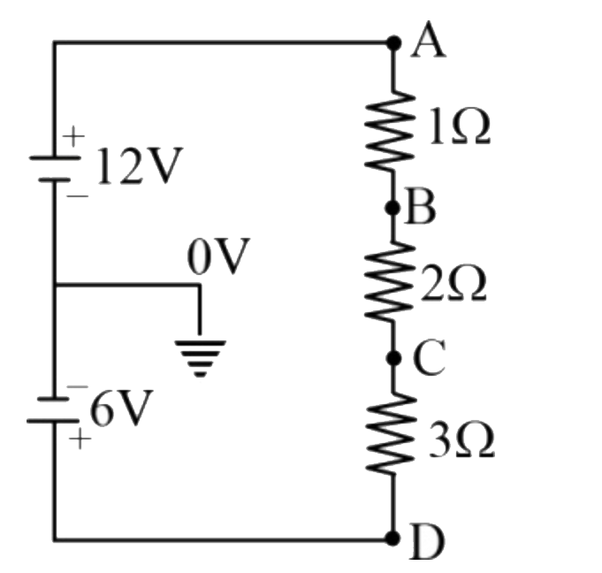 A12V,10V,6VB11V,9V,6VC11V,9V,0VD12V,10V,0V
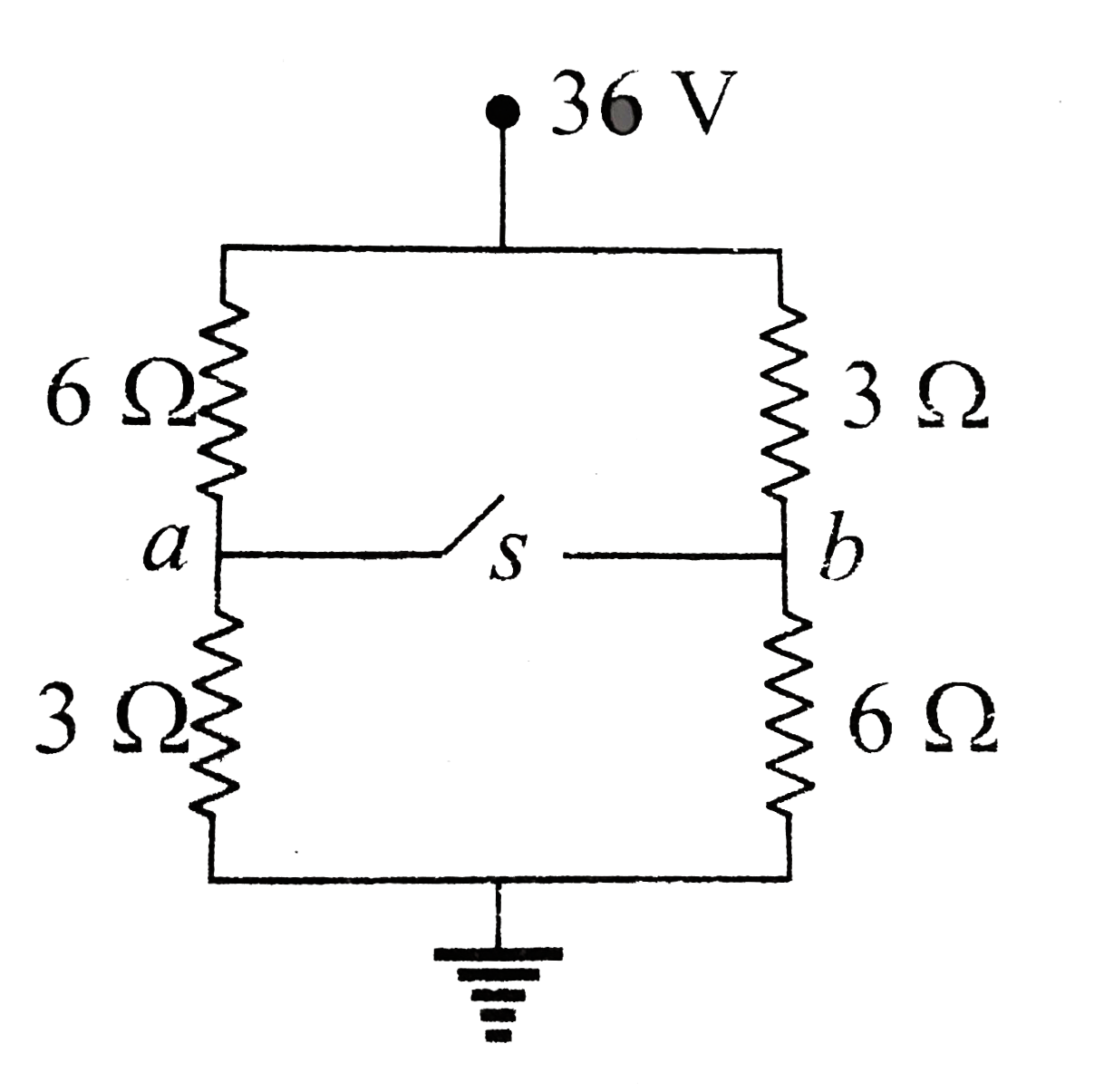
In the circuit shown in fig. calculate the following:
a. Potential differece between points a and b when switch S is open.
b.Current through S in the circuit
View Solution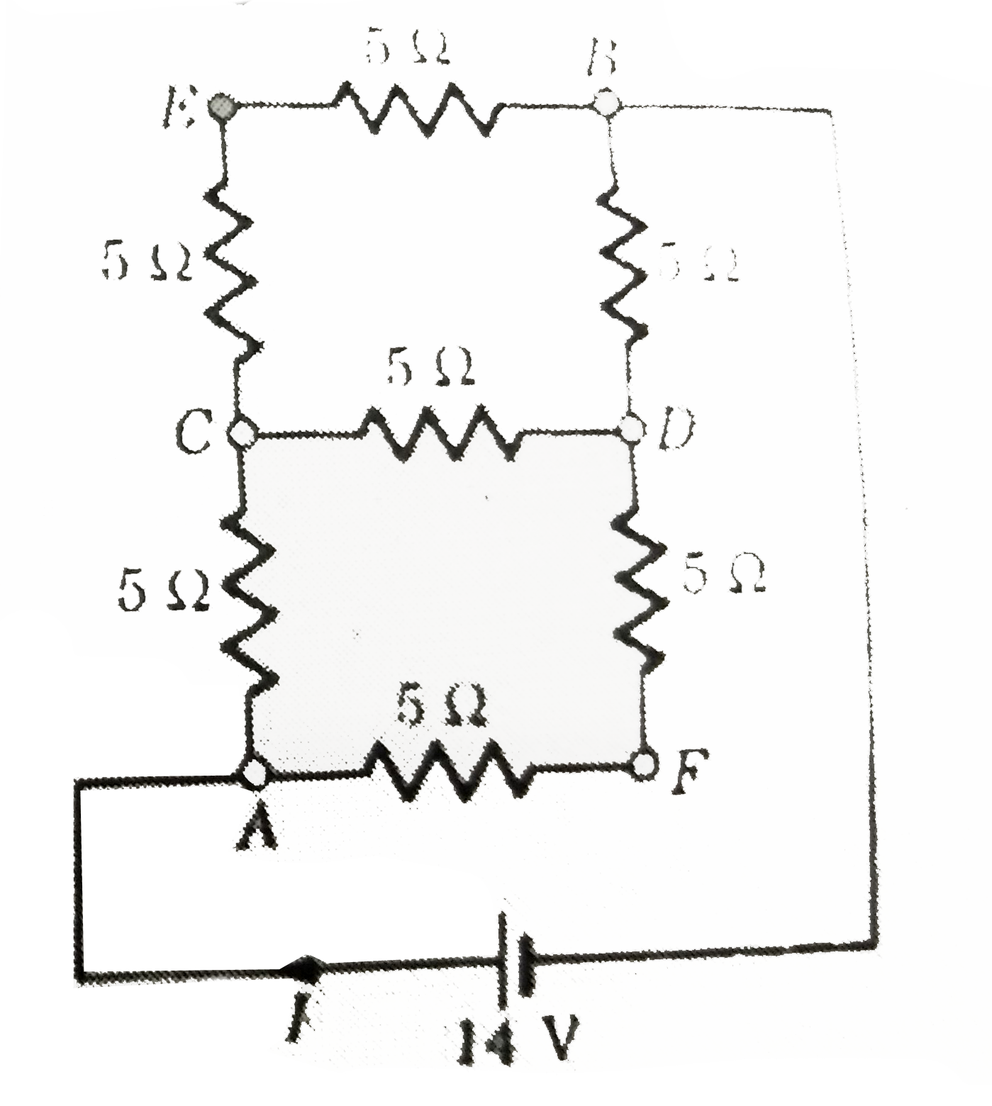
In the circuit shown in figure. Determine the current in the resistance CD and equivalent resistance between the points A and B. the iternal resistance of the cell is negligible.
View SolutionAn electric circuit is shown in figure.The potential difference between the point A and B is. (A) 103 (B) 203 (C) 53 (D) 73
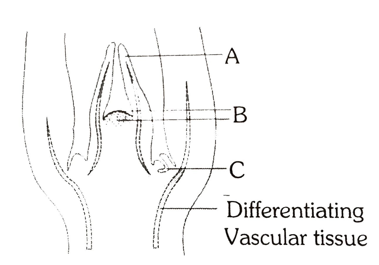
View SolutionIdentify the following point A, B and C in the given diagram
View SolutionIn the circuit shown in the figure , if a conducting wire is conneted between point A and B , thent the current in the wire AB will
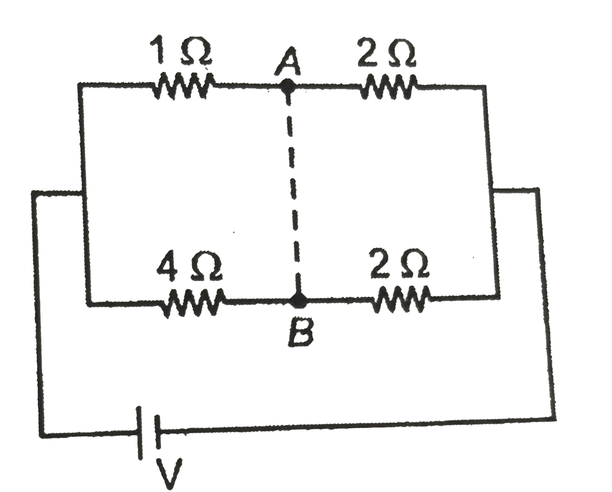
View Solution

_S01_003_Q01.png)
