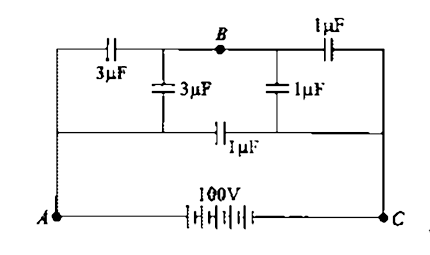
(a) Taking the potential at the point B to be zero, find the potential of point D.
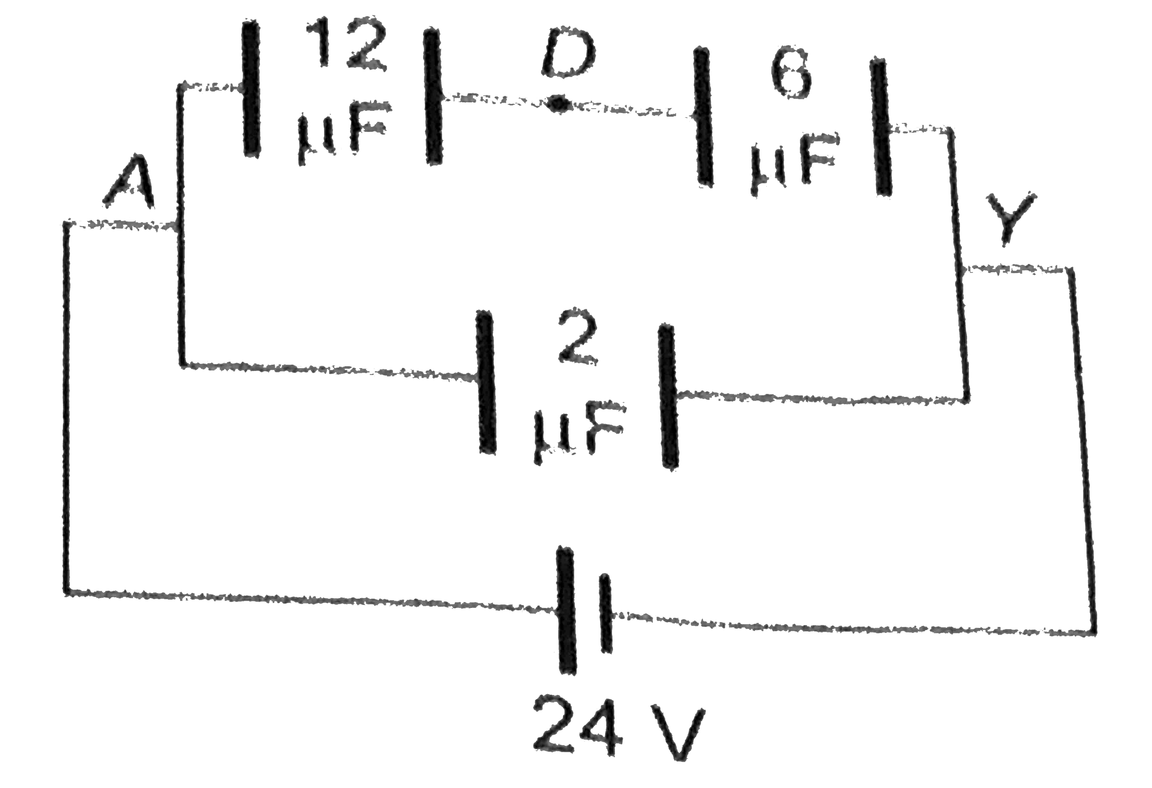
(b) Find VA−VB. Under what condition is it equal to zero.
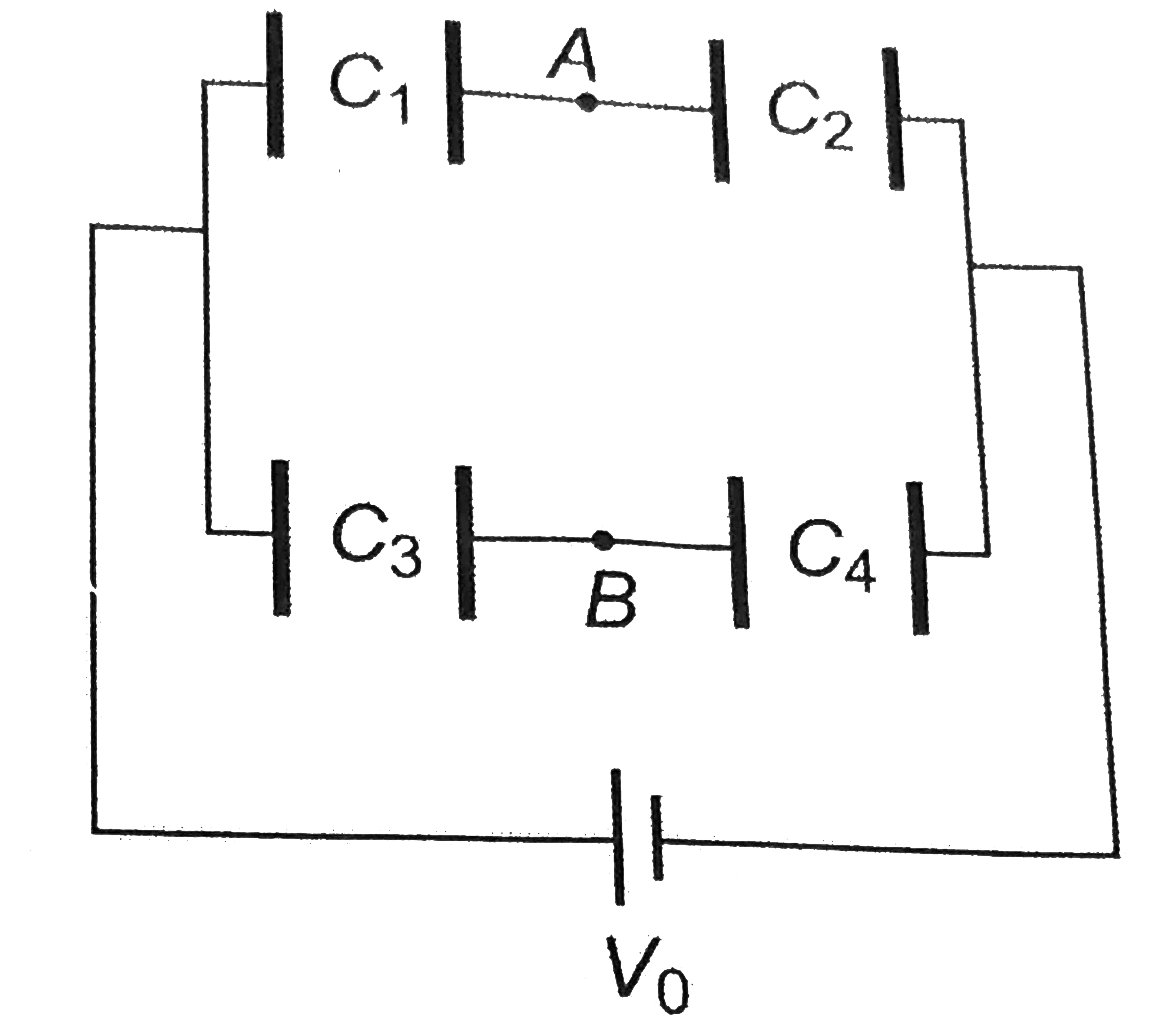
(c) Consider the situation as shown in diagram. How much charge will flow through cell if the switch S is closed?
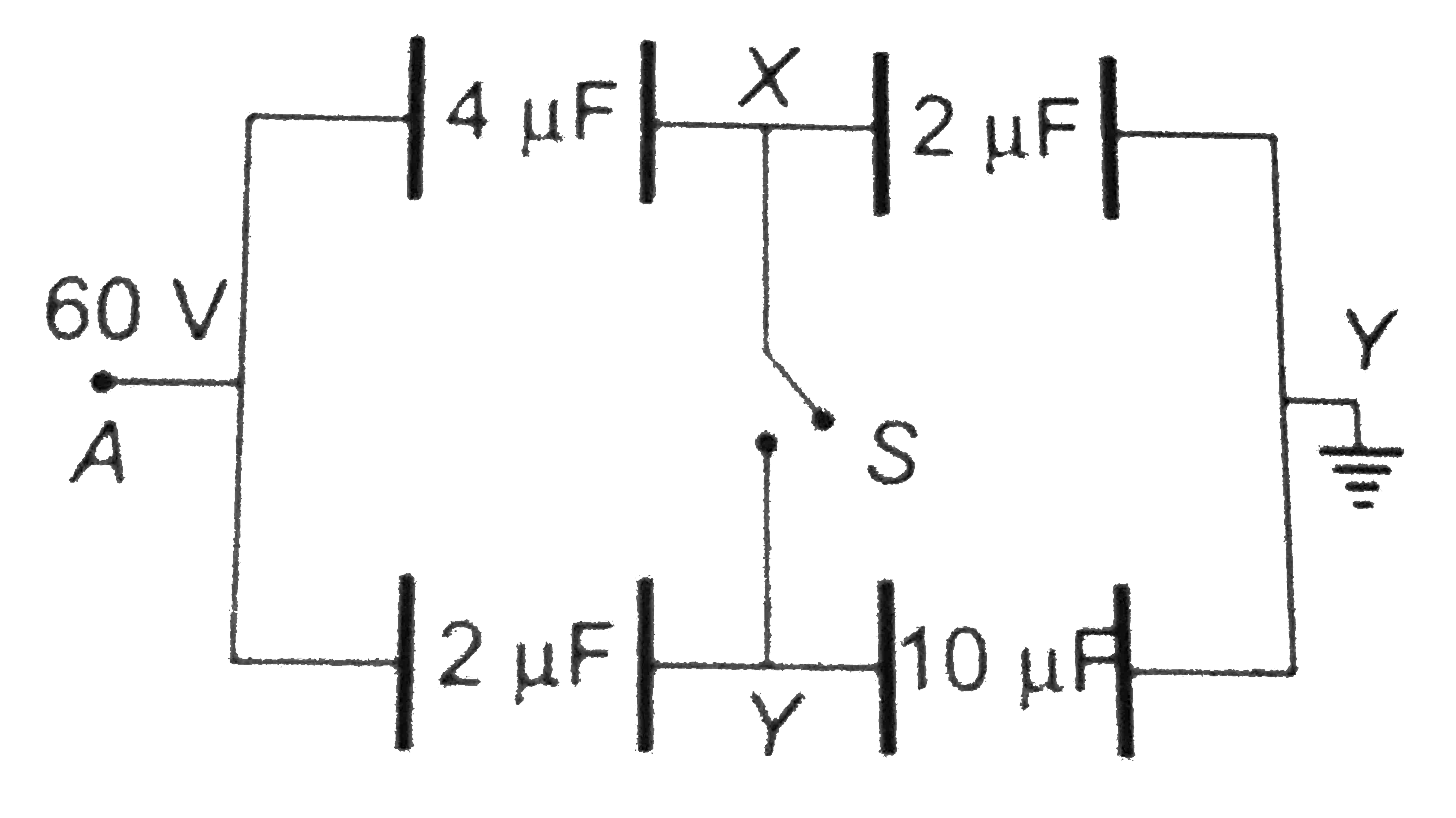
(d) In the circuit shown in the figure, calculate
(i) Potential difference between the points X and Y.
(ii) Potential of the point X when switch S is closed.
(iii) Charge flown through the switch when it was closed.

Video Solution
Text Solution
(a) 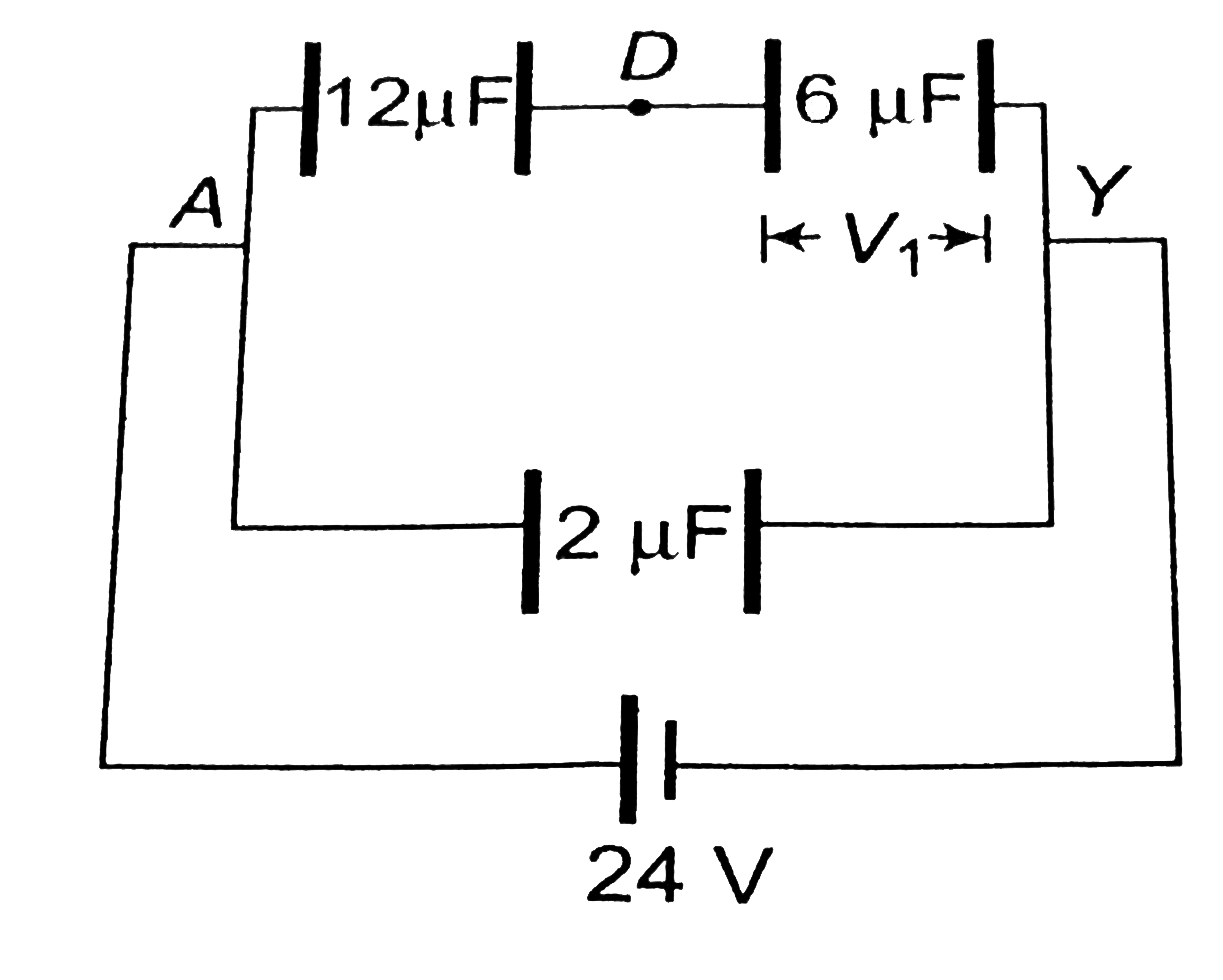
V1=(1212+6)×24=16V
potential of capacitor means potential difference between its plates.
V1=VD−VB=16
VB=0
VD=16V
(b) 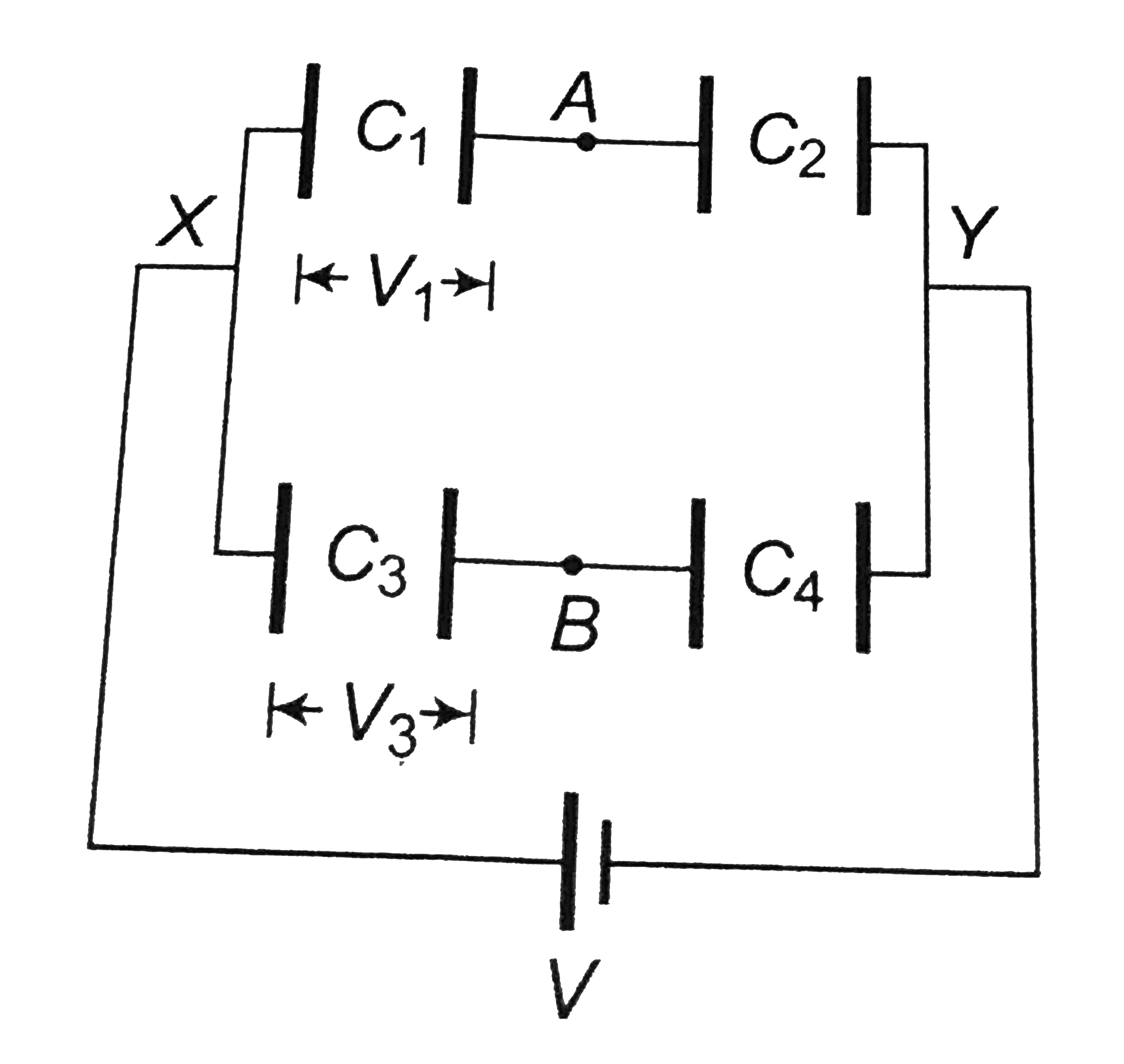
V1=(C2C1+C2)V,V3=(C4C3+C4)V
V1=VX−VA=C2VC1+C2 ...(i)
V3=VX−VB=C4VC3+C4
Subtracting (i) from (ii), we get
VA−VB=(C4C3+C4−C2C1+C2)V
If VA−VB=0
C4(C1+C2)=C2(C3+C4)
C1C2=C3C4
(c) when switch S is open:
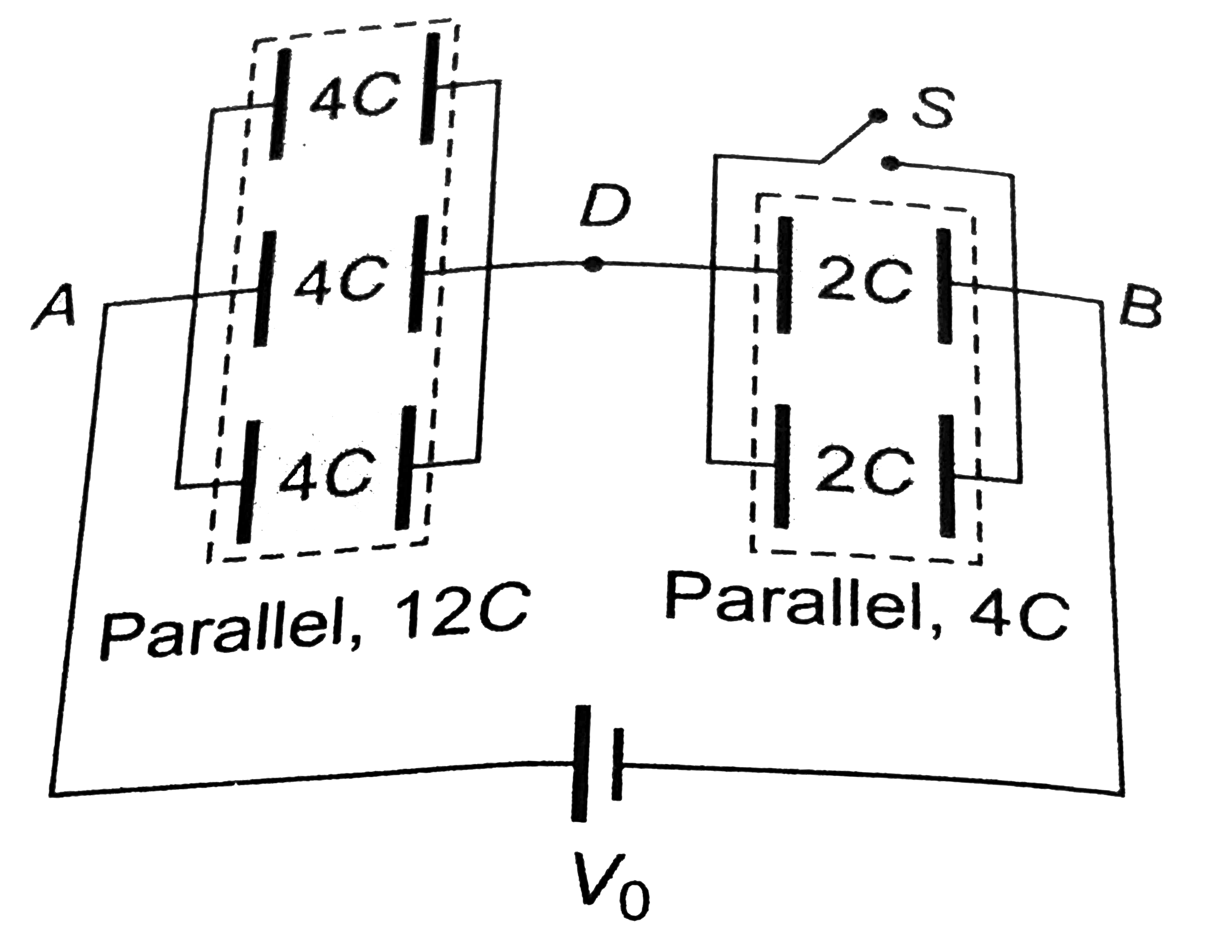
Ceq=12C×4C12C×4C=3C
Charge suppplied by battery Q1=3CV0
When switch S is closed:
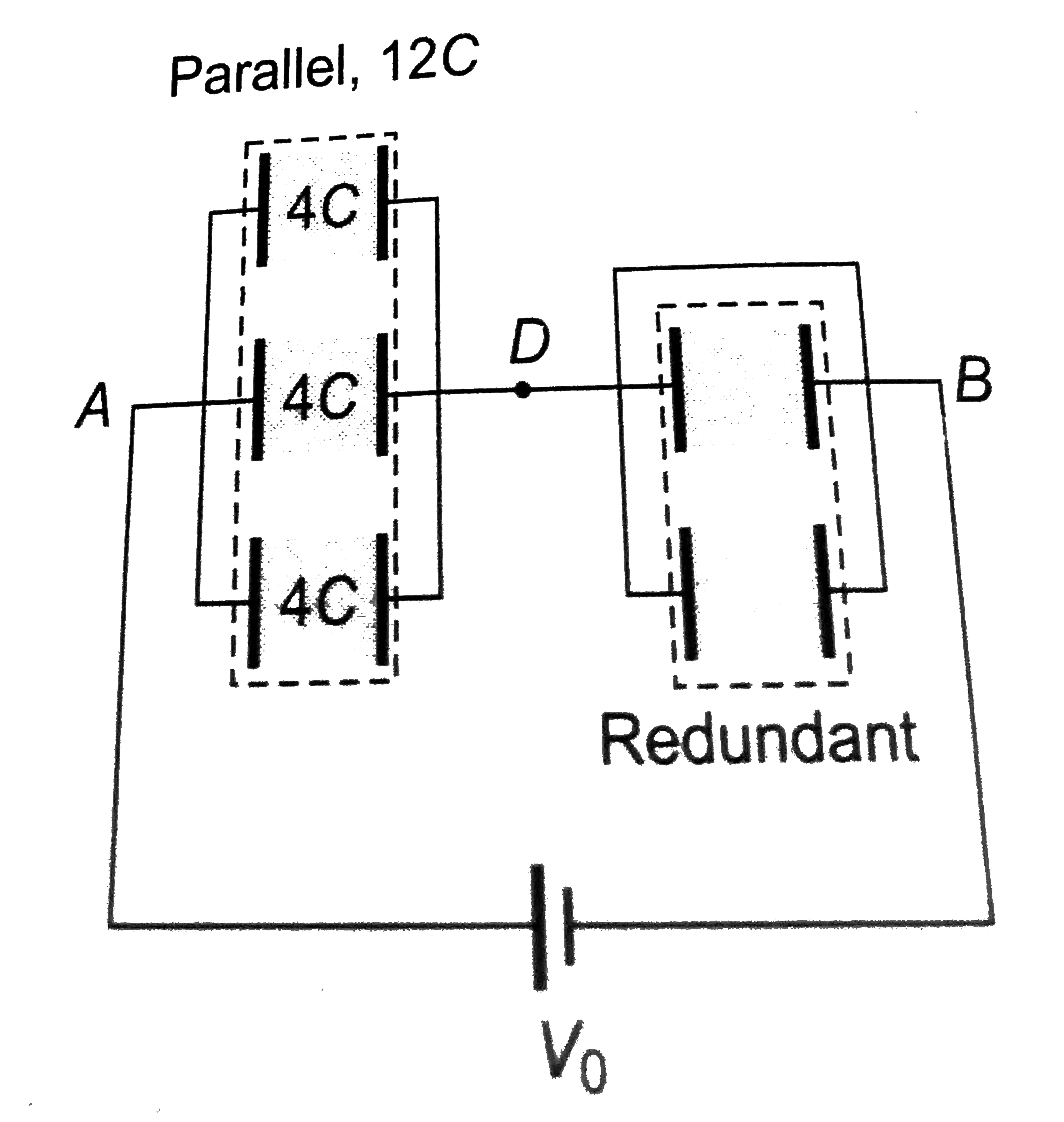
Points D and B are at same potential after closing the switch, the capacitors between D and B are redundant, remove them.
Ceq=12C
Charge on capacitors, Q2=12CV0
Charge supplied buy battery after closing the switch
ΔQ=Q2−Q1=12CV0−3CV0=9CV0
(d) (i) 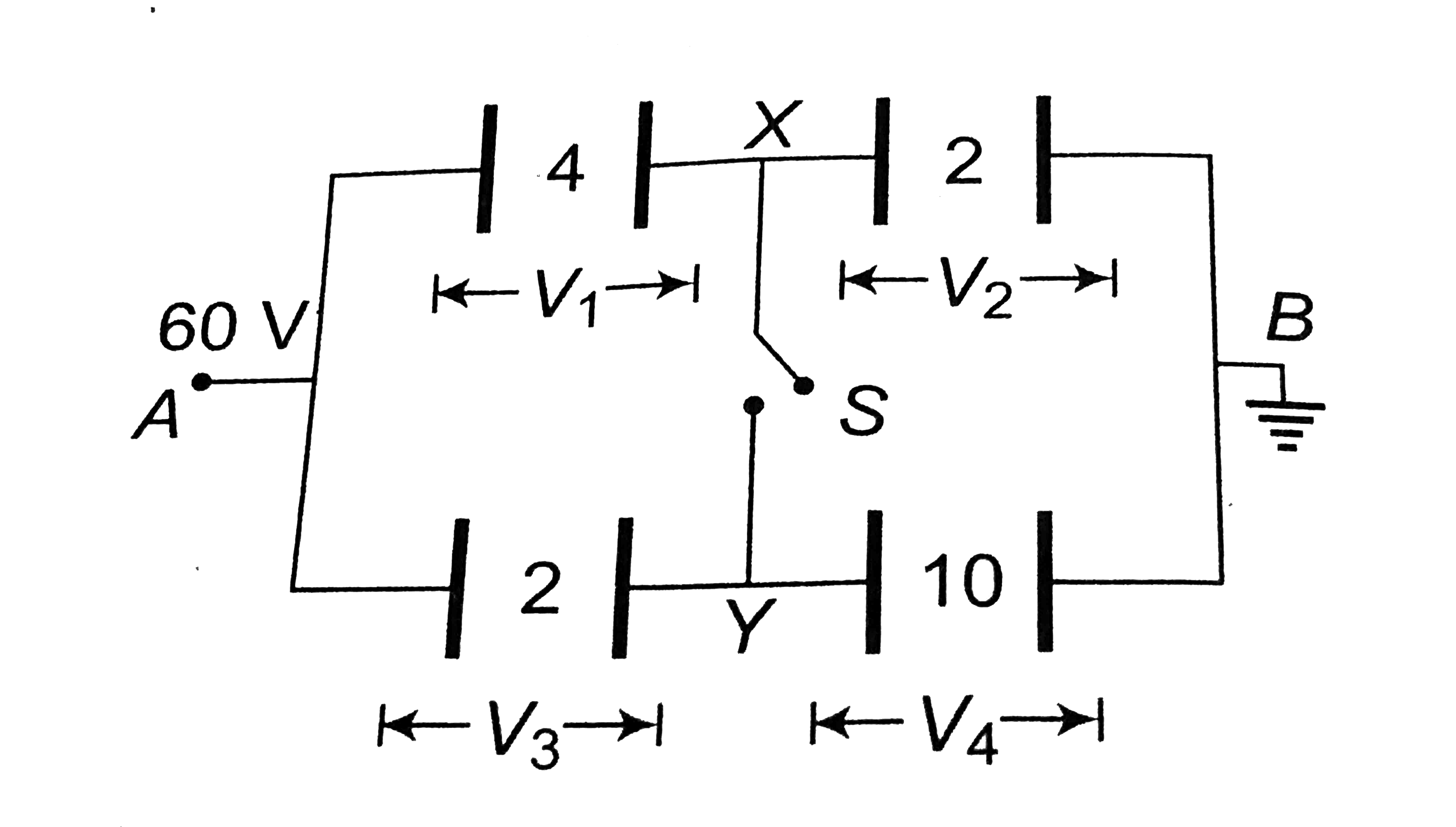
since point B is connected to earth, VB=0,VA=60V
VA−VB=60V
V2=(44+2)×60=40V
V4=(22+10)×60=10V
V2=VX−VB=40 implies Vx=40V
VX−VY=40−10=30V
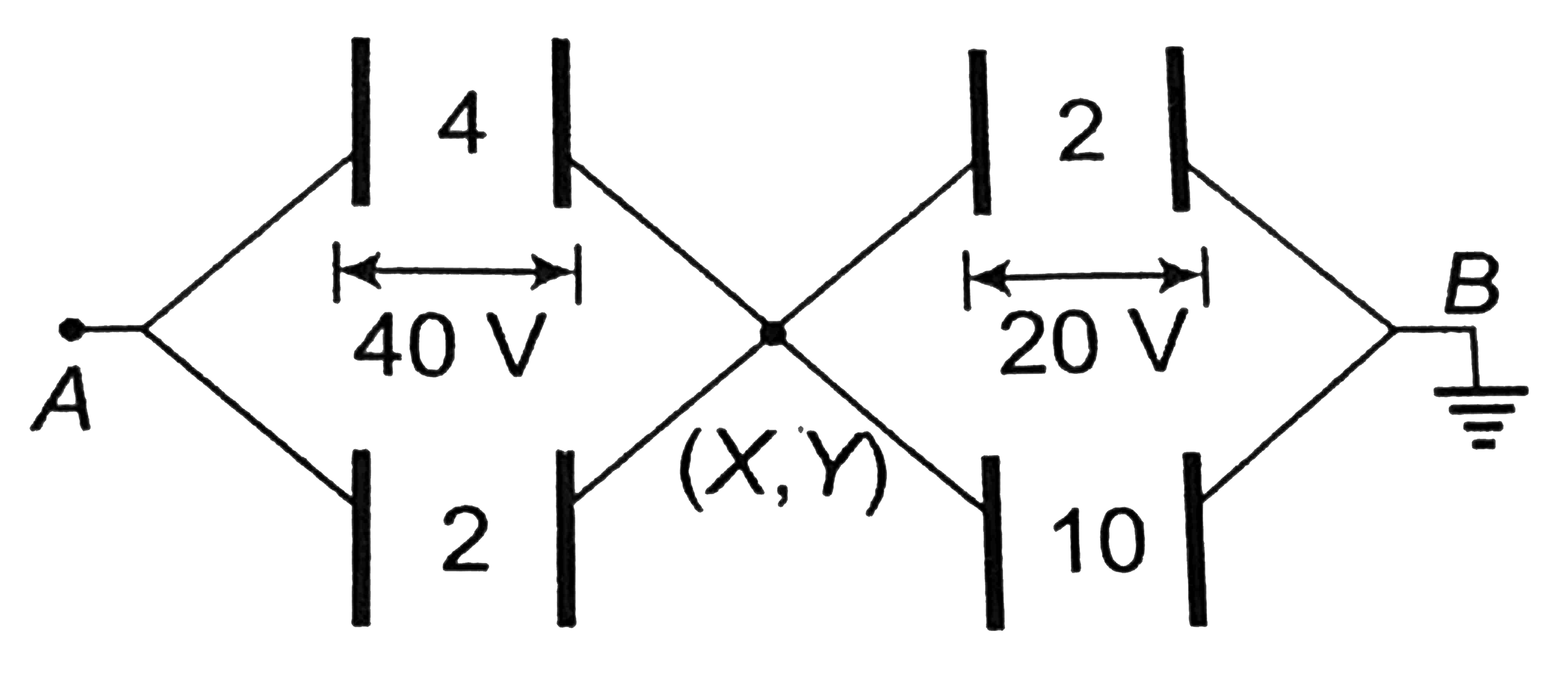
(ii) Now switch S is closed, points X and Y are are at same potential.

V1=(126+12)×60=40V, Now return to previous diagram.

V2=60−VX−VB=20⇒VX=20VV1=20V
Now return to previous diagram
VX−VB=20⇒VX20V
(iii) Charge on 4μF,4×40=160μC
Charge on 2μF,2×20=40μC Charge flown through switch=160−40=120μC

|
Topper's Solved these Questions
Similar Questions
Knowledge Check
In the circuit shown in figure potential difference between the points A and B in the steady state is
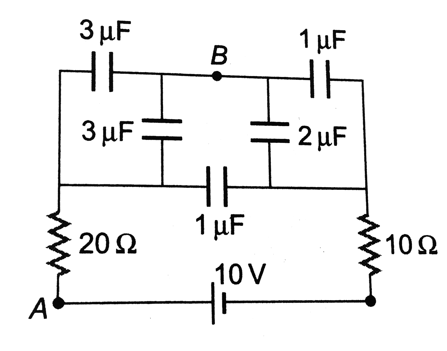 AzeroB6VC4VD103V
There is a electric circuit as shown in the figure. Find potential difference between points a and b.
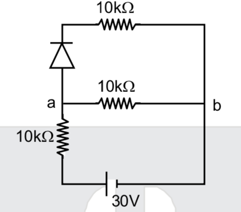 A3VB15VC10VD5V
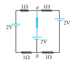
For the circuit figure, find the potential difference between points a and b:
 A2.4VB2.8VC2VD3.2v
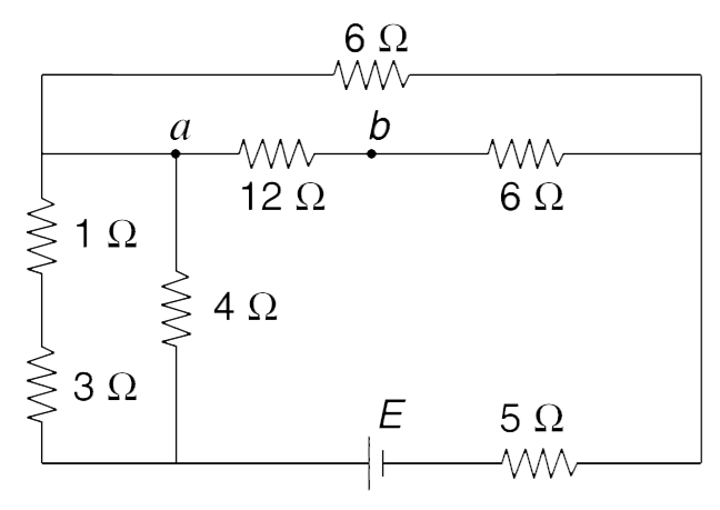
In the circuit shown in the figure, the potential difference between points aandb is Va−Vb=4V. Find the emf, E of the battery.
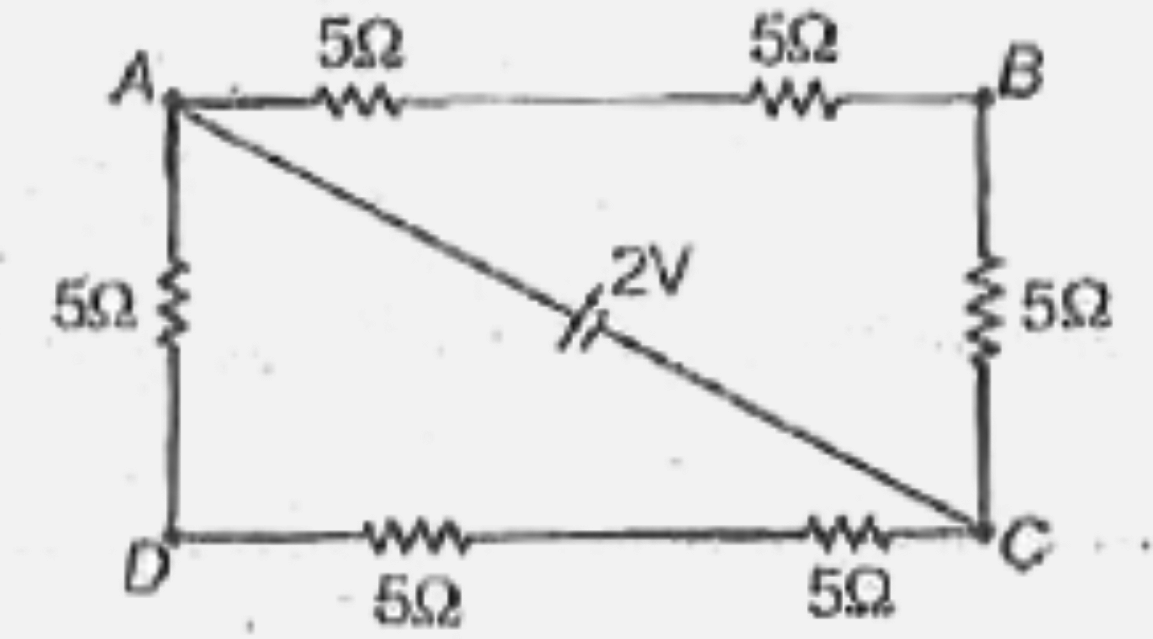
View SolutionFind the potential difference between points B and D in the figure below.
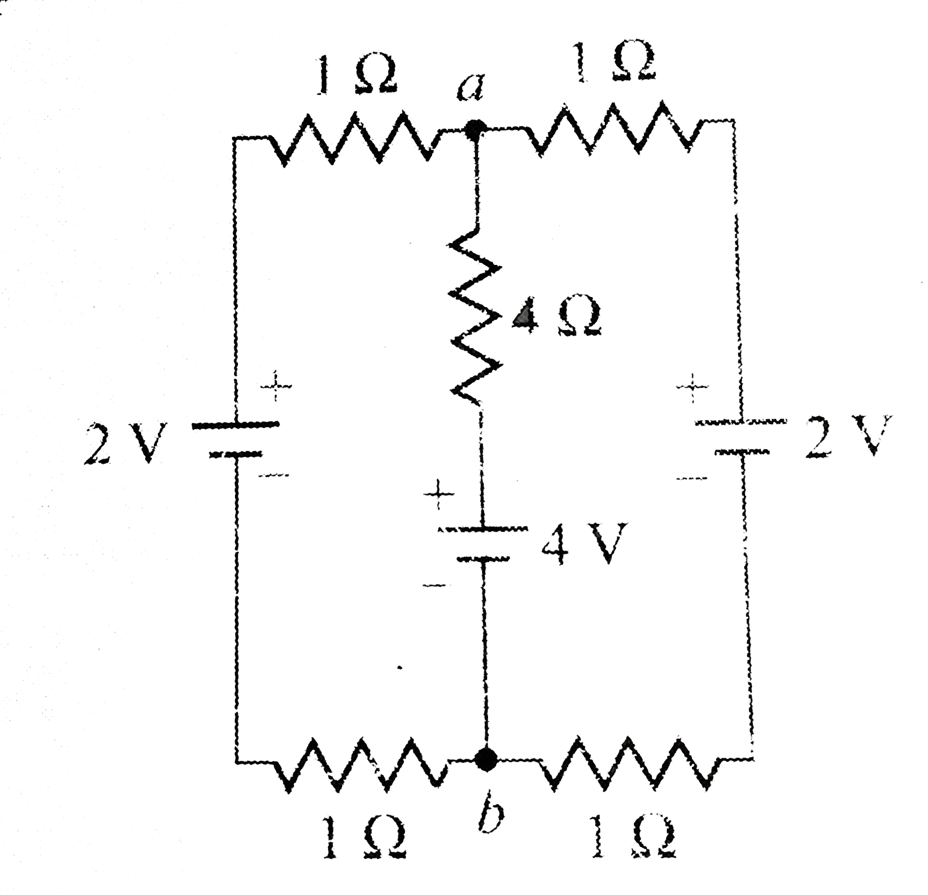
View SolutionFor the circuit given in figure, find the potential difference between points a and b.
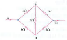
View SolutionIn the circuit it shown in the figure, the value of Resistance X, when potential difference between the points B and D is zero will be
View SolutionIn the part of a circuit shown in figure, the potential different
(VG−VH) between points G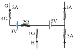
View Solution

