(i) calculate the value of output voltage V0 and current I if silicon diode and germanium diode conduct at 0.7V and 0.3V respectively. Fig.
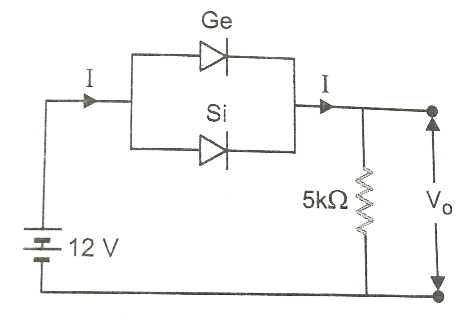
(ii) If now germanium diode is cinnected to 12V in reverse polarity, find new values of V0 and I.
As Ge diode conducts at 0.3V, both Ge and Si are in parallel, so p.d. across each is 0.3V.
At 0.3V, Si diode offers infinite resistance and it does not conduct.
p.d. across R=5kΩ is
12−0.3=11.7V
V011.7V
i=V0R=11.75×103=2.34mA
When the connection of Ge diode are reversed, it will be in reverse biased and for conduction, the p.d. across the silicon diode will be 0.7V
p.d. across R=5kΩ is
12−0.7=11.3V
V0=11.3V
i=V0R=11.35×103=2.26mA
Topper's Solved these Questions
- SEMICONDUCTORSBOOK - CP SINGHCHAPTER - SEMICONDUCTORSEXERCISE - Exercises
140 Videos
- REFRACTION OF LIGHT BY PLANE SURFACESBOOK - CP SINGHCHAPTER - REFRACTION OF LIGHT BY PLANE SURFACESEXERCISE - Exercises
110 Videos
- THERMAL AND ELECTRIC EFFECT oF CURRENTBOOK - CP SINGHCHAPTER - THERMAL AND ELECTRIC EFFECT oF CURRENTEXERCISE - Exercises
101 Videos
Similar Questions
Calculate the value of output voltageV0 and I if the Si diode and the Ge diode conduct at 0.7 V and 0.3V respectively, in the circuit given in Fig. If now Ge diode connections are reversed, what will be the new values of V0 and I.
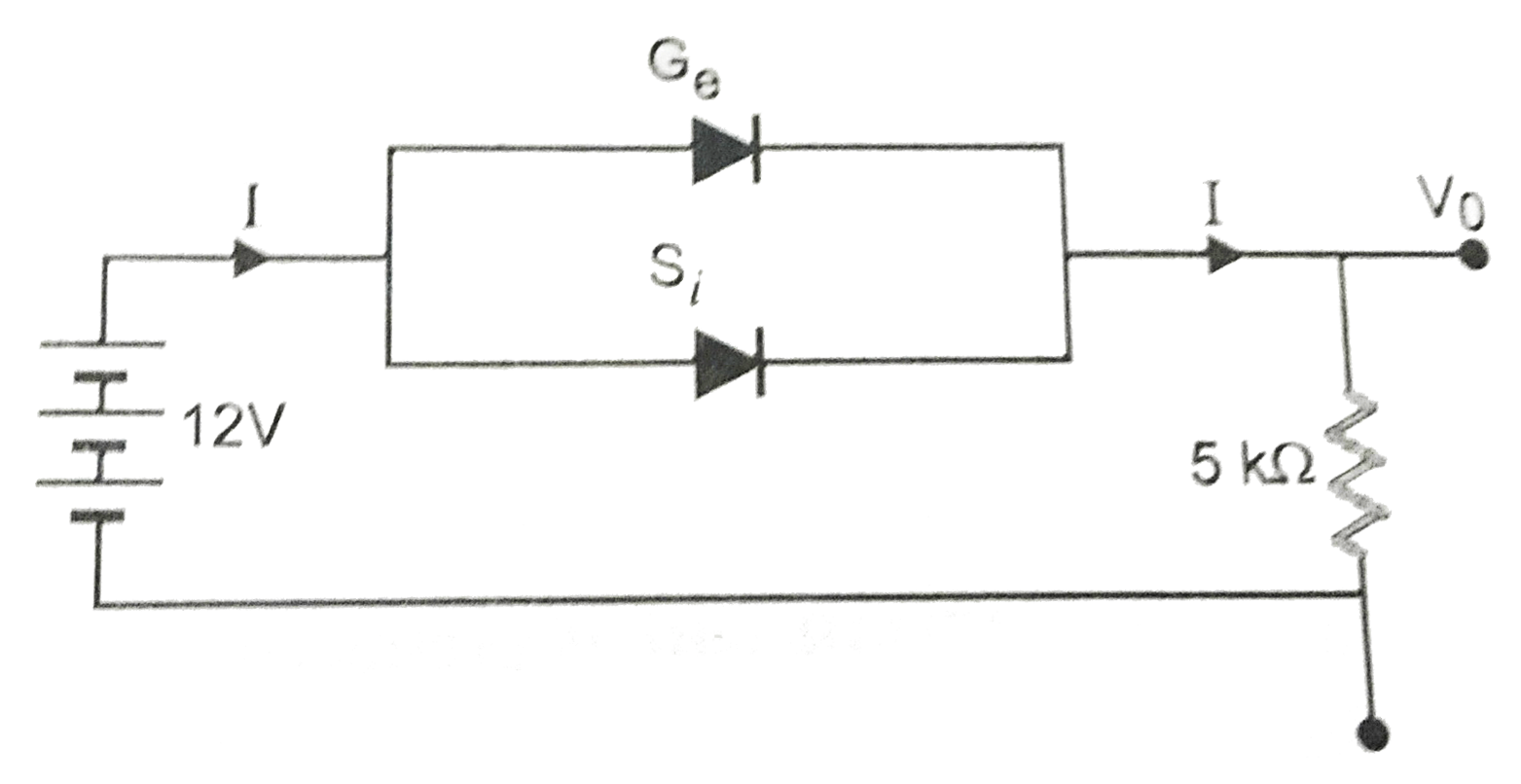
View SolutionCalculate the value of output voltageV0 and I if the Si diode and the Ge diode conduct at 0.7 V and 0.3V respectively, in the circuit given in Fig. If now Ge diode connections are reversed, what will be the new values of V0 and I.

View Solution
Knowledge Check
In the circuit shown in figure, the silicon and germanium diodes start conducting at 0.7 V and 0.3 V respectively. What are the values of V0 and I?
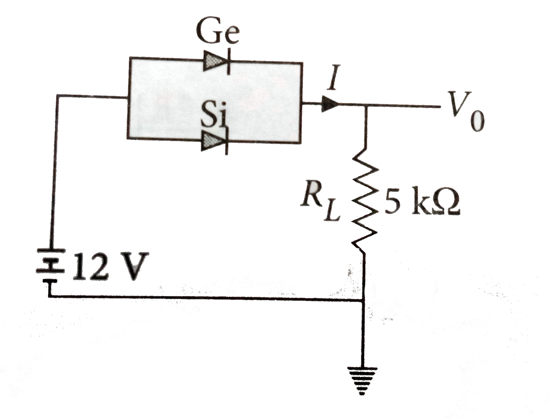 A12 V, 2.4 mAB11.7 V, 2.34 mAC11.3 V, 2.26 mAD11 V, 2.2 mA
Ge and Si diodes conduct at 0.3V and 0.7V respectively. In the following figure if Ge diode connection are reversed, the value of V0 changes by
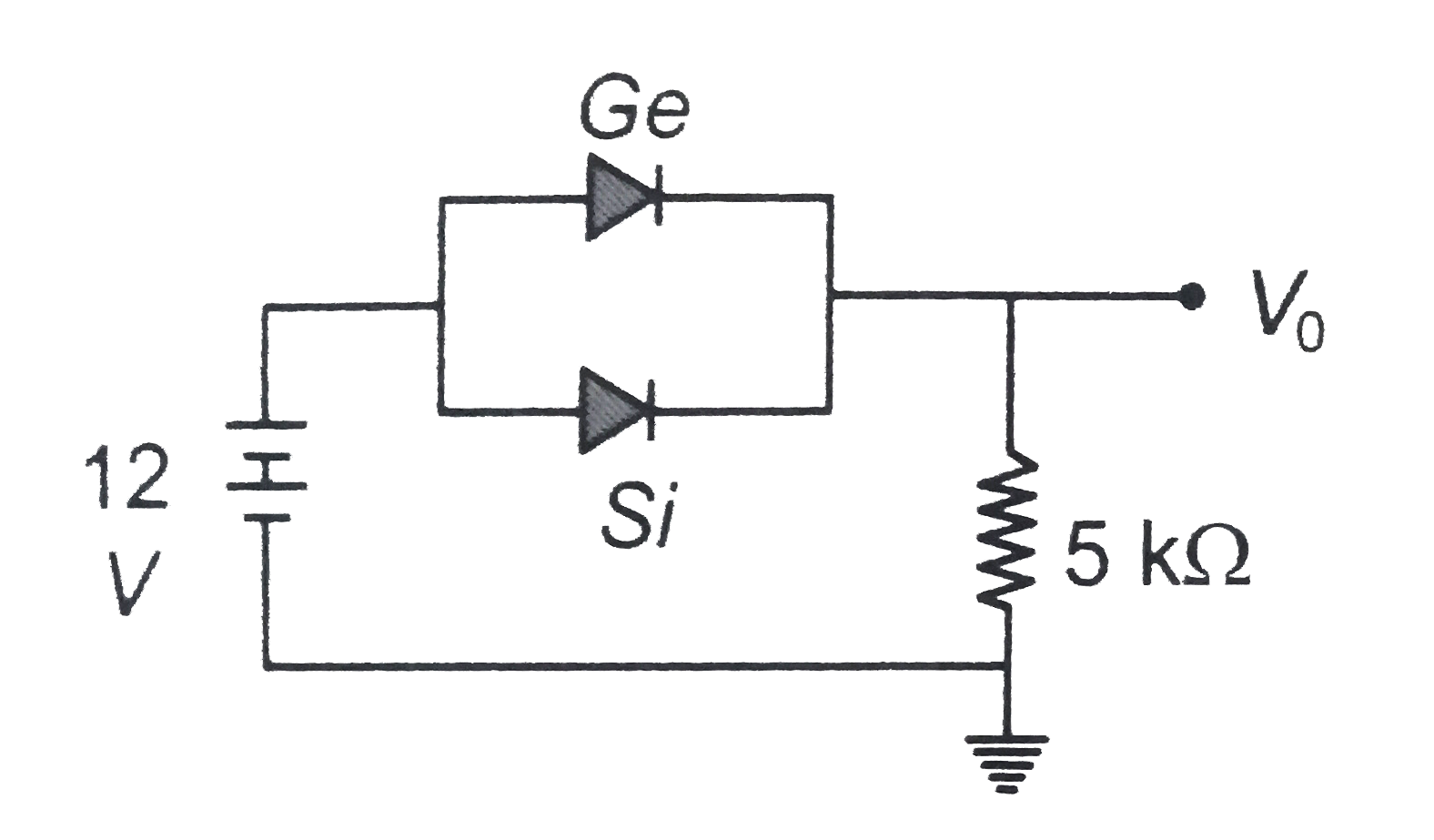 A0.2VB0.4VC0.6VD0.8V
The resistance of a germanium junction diode whose V−I is shown in figure is (Vk=0.3V)
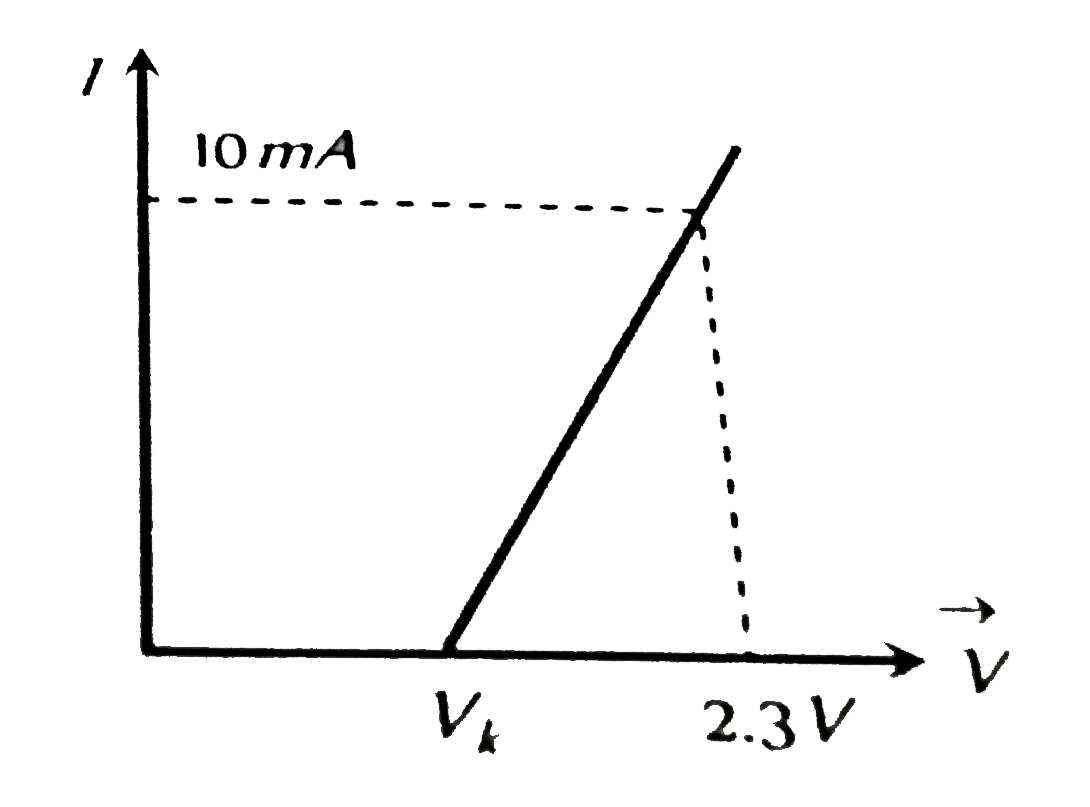 A5kΩB0.2kΩC2.3kΩD(102.3)kΩ
Consider a silicon diode with a threshold voltage of −0.7V, used as a half wave rectifier. Draw the output if the input is a sine wave from of amplitude 2V and circuit is on in reverse position.
View SolutionThe values of v and I for silicon diode is given as follows

Using the data calculate the forward and reverse bias resistance of silicon diode
View SolutionAssuming that the silicon diode (having negligible resistance) the current through the diode is (knee voltage of silicon diode is 0.7V)

View SolutionIn a voltage regulating of zener diode, the graph of output voltage vo versus input voltage v1 is
View SolutionWhen the reverse potential in a semiconductor diode are 10 V and 30 V, thent he corresponding reverse currents are 25μA. And 50μA respectively. The reverse resistance of junction diode will be-
View Solution
