In the given circuit, K1 and K2 are open initially and the capacotors are uncharged, After K1 and K2 are closed and steady state is attained. Now answer the following questions.
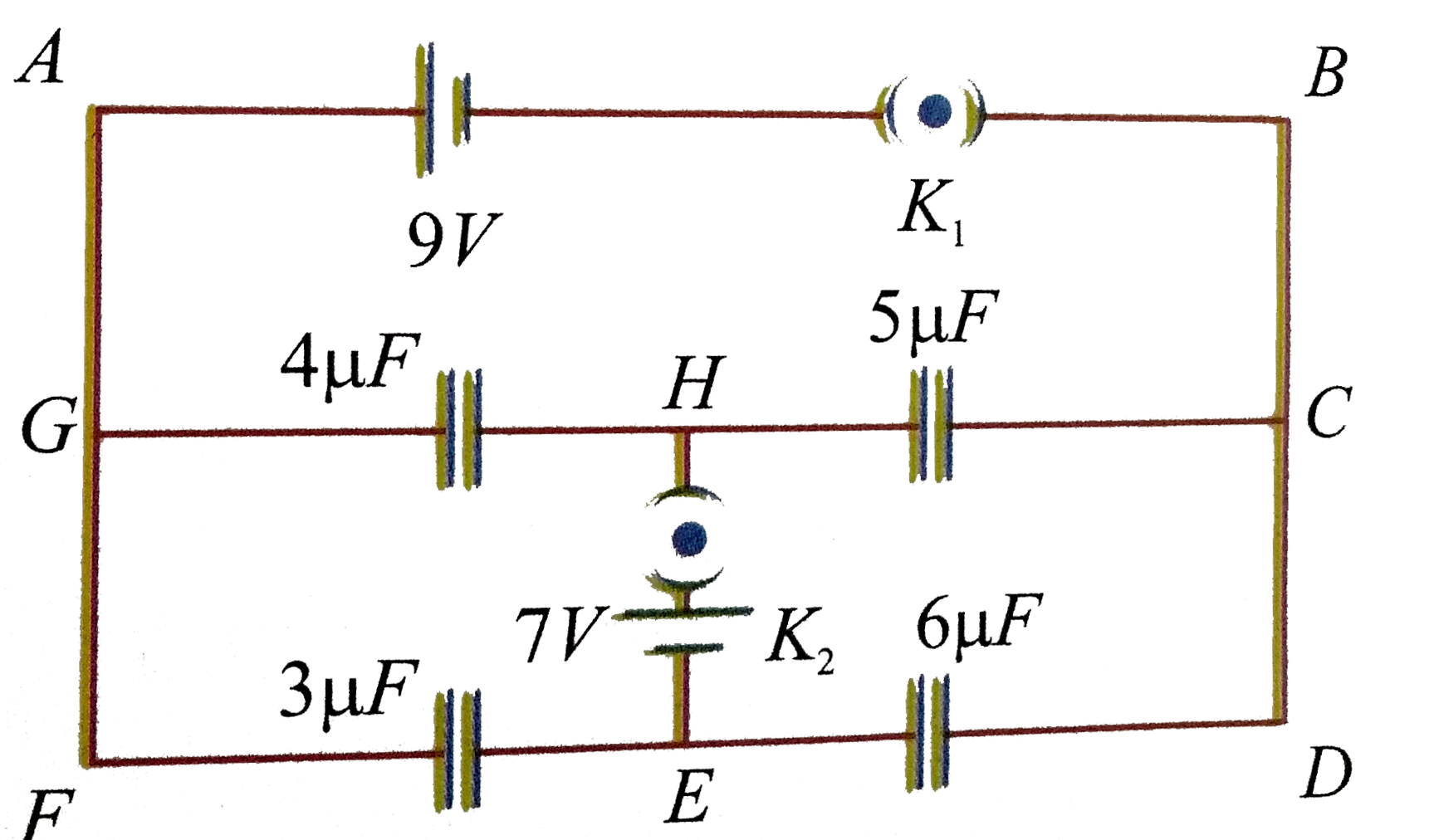
The charge on 4μF capacitor is :
8μc
35μc
6μc
zero
The correct Answer is:A
Step by step video, text & image solution for In the given circuit, K_(1) and K_(2) are open initially and the capacotors are uncharged, After K_(1) and K_(2) are closed and steady state is attained. Now answer the following questions. The charge on 4 mu F capacitor is : by Physics experts to help you in doubts & scoring excellent marks in Class 12 exams.
Updated on:21/07/2023Topper's Solved these Questions
- CAPACITANCEBOOK - NARAYNACHAPTER - CAPACITANCEEXERCISE - Level-VI
28 Videos
- CAPACITANCEBOOK - NARAYNACHAPTER - CAPACITANCEEXERCISE - Subjective
9 Videos
- CAPACITANCEBOOK - NARAYNACHAPTER - CAPACITANCEEXERCISE - NCERT Based
13 Videos
- ATOMS BOOK - NARAYNACHAPTER - ATOMS EXERCISE - EXERCISE -4
47 Videos
- COMMUNICATION SYSTEMBOOK - NARAYNACHAPTER - COMMUNICATION SYSTEMEXERCISE - Level-II(H.W)
25 Videos
Similar Questions
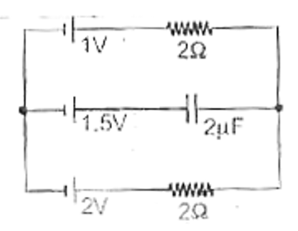
The charge in the 2μF capacitor at steady state is
View SolutionIn the circuit shown in Fig, instially K1 is closed and K2 is open . What are the charges on each capacitor.
Then K1 was opened and K2 was closed (order is important). What will be the charge on each capacitor now ? [C=1μF]
View Solution
Knowledge Check
In the given circuit, K1 and K2 are open initially and the capacotors are uncharged, After K1 and K2 are closed and steady state is attained. Now answer the following questions.
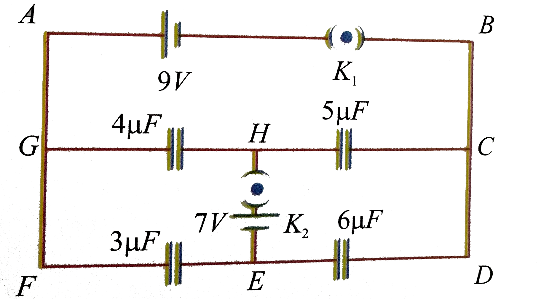
The charge in 3μF capacitor is :A8μcB35μcC27μcDzeroIn the given circuit, K1 and K2 are open initially and the capacotors are uncharged, After K1 and K2 are closed and steady state is attained. Now answer the following questions.
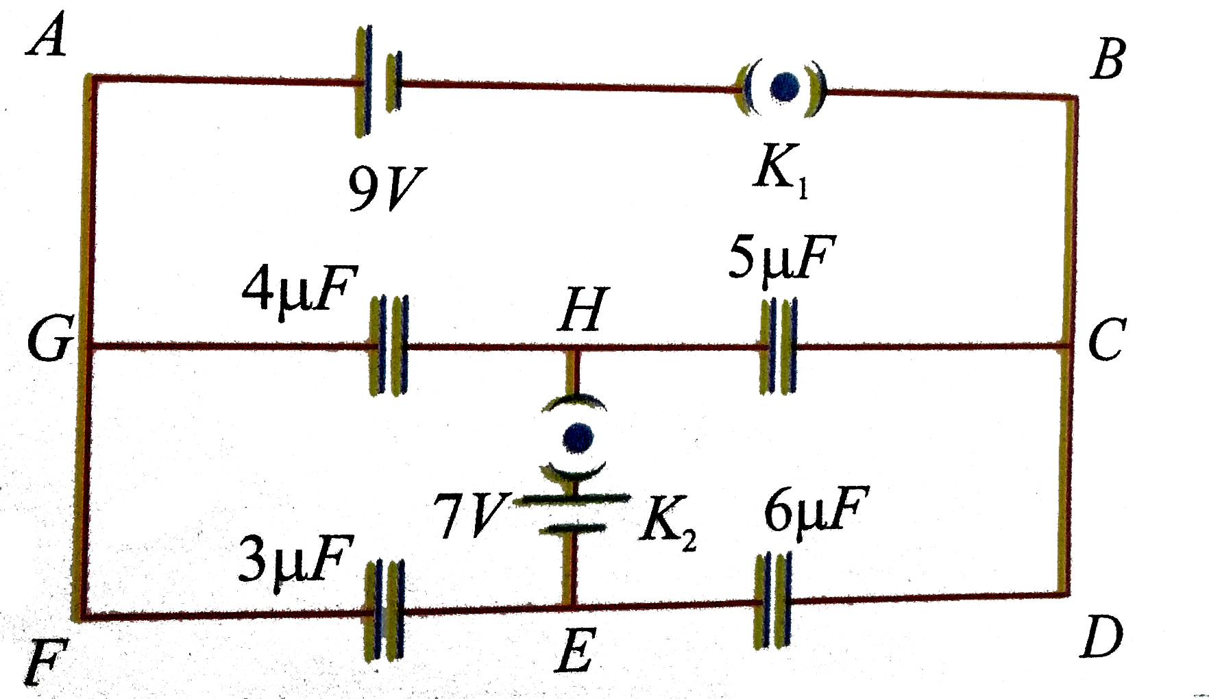
The charge on 5μc capacitor is :A8μcB35μcC6μcDzeroFour capacitor and a battery of emf24V are connected as shown in the figure. Initially, S is open and the capacitors are uncharged. After S is closed and steady state is attained, the potential difference across the 4μf capacitor is 7.5V. The capacitance in μf of the capacitor A is.
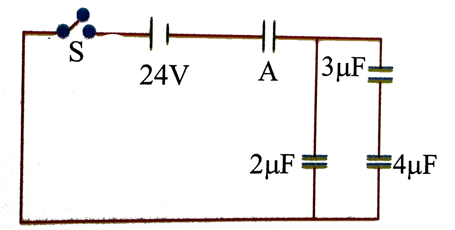 .A5B7C8D10
The figure shown is part of the circuit at steady state

The charge on 2μF capacitor is :
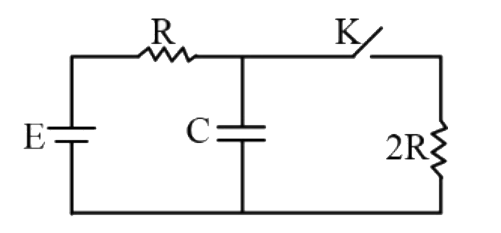
View SolutionIn the given circuit switch K is open. The charge on the capacitor is C is steady-state is q1 Now the key is closed and steady-state charge on C is q2 The ratio of charges q1/q2 is -
View SolutionWe have two capacitors C1andC2 of capacitance 12μF and 6μF respectively. As shown in the given circuit arrangement the two capacitors are joined to a power supply of 6 volts. Initially the switch S1 is closed but switch S2 is open. After some time, the switch S1 is opened and simultaneously switch S2 is closed.
Now answer the following questions :
The final value of charge on capacitor C2 is
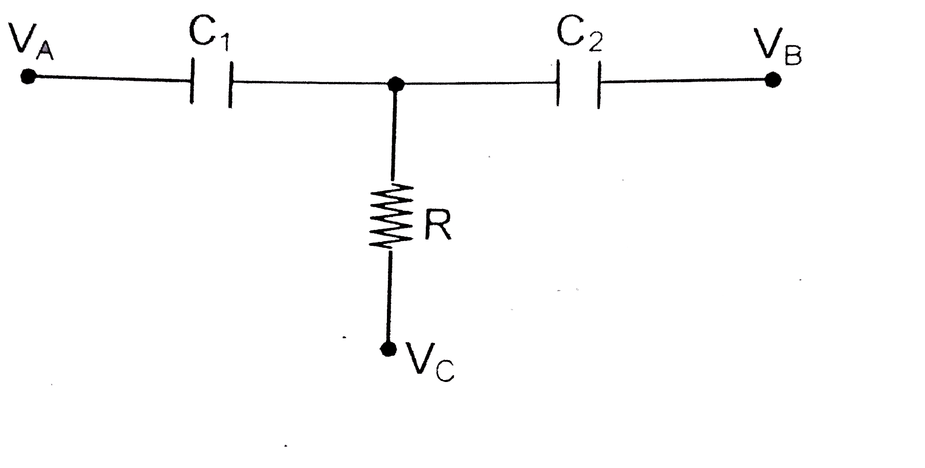
View SolutionFor given circuit charge on capacitor C, and C2 in steady state will be equal to
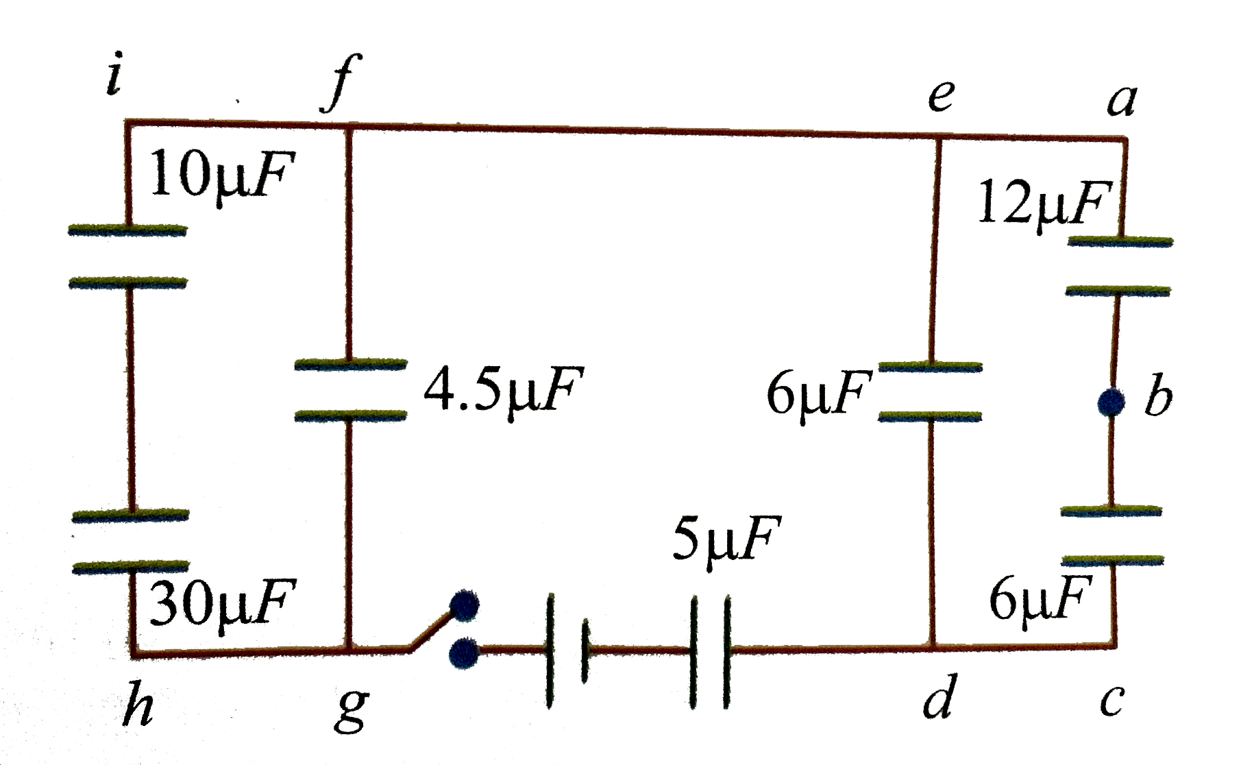
View SolutionIn the circuit diagram shown here seven capacitors are connected to a source of emf E. Initially, the switch S is closed and steady state attained. Now, the potential difference between the points 'a' and 'b' is 4 volt. Now, answer the following :
 .
.
The charge on 4.5μF is :
View Solution
