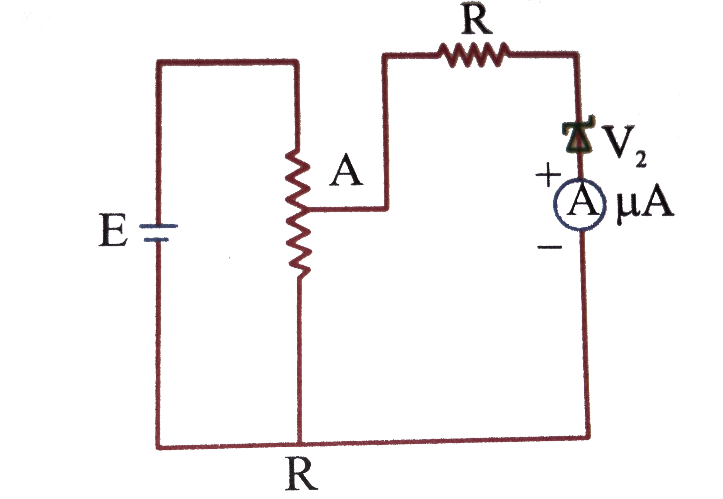
Zenar diode is operating the reverse bias the breakdown region for which the circuit diagram is as shown in the figure here take Vz=7V and R=10KΩ For porential differe is equal to 8v across AD. What is the current through micrometer
1000μA
1mA
10μA
100μA
The correct Answer is:D
write KVL equation
1R=VBA−VX=8−7
I=1V10kΩ=100μA
Topper's Solved these Questions
- EXPERIMENTAL PHYSICSBook:NARAYNAChapter:EXPERIMENTAL PHYSICSExercise:Level-v(Single answer)
Explore 23 Videos
- EXPERIMENTAL PHYSICSBook:NARAYNAChapter:EXPERIMENTAL PHYSICSExercise:Multiple answer
Explore 6 Videos
- ELECTROSTATICS AND GAUSS LAWBook:NARAYNAChapter:ELECTROSTATICS AND GAUSS LAWExercise:Intergers type question
Explore 11 Videos
- MAGNETISMBook:NARAYNAChapter:MAGNETISMExercise:LEVEL-II (H.W)
Explore 24 Videos
Similar Questions
In the circuit shown in figure

E1=10V,E2=4V,r1=r2=1Ω and R=2Ω.
Find the potential difference across battery 1 and battery 2.
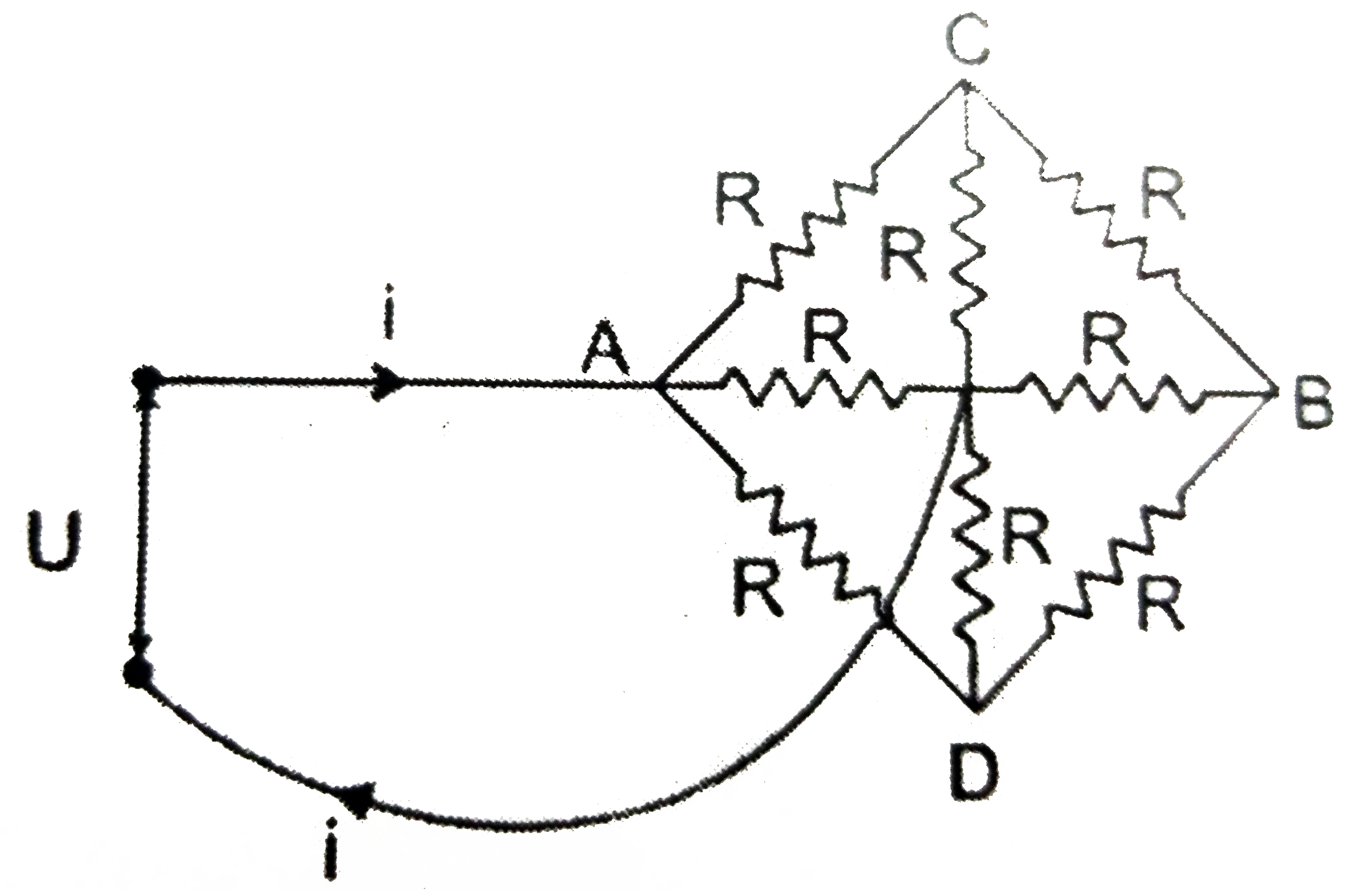
View SolutionThe resistance of each resisor in the circuit diagram shown in figure is the same and equal to R=1Ω The voltage across the terminals is U = 7V. Determine the current current i(Ampere) the jeads if their resistance can be neglected.
View Solution
Knowledge Check
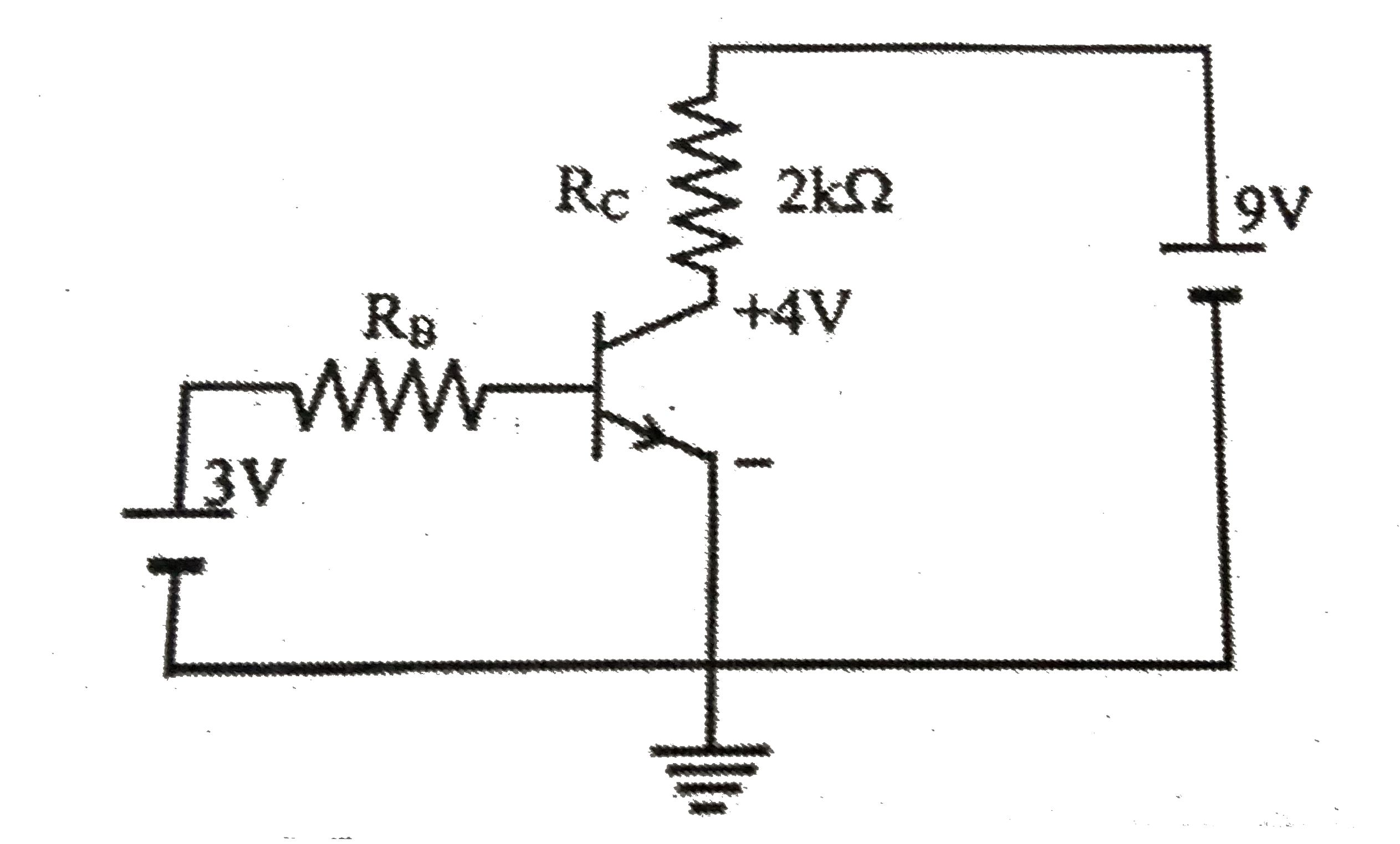
What is the base resistance RB in the circuit as shown in figure , if βd.c.=90,VBE=0.7V,VCE=4V?
 A29KΩB82KΩC108KΩD55KΩ
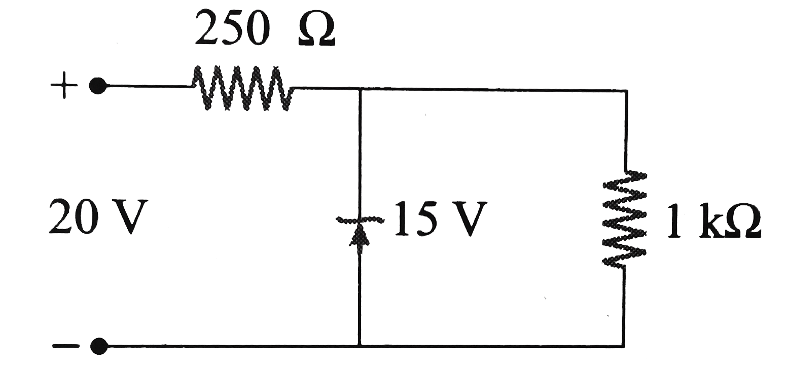
A zener diode, having breakdown voltage equal to 15V is used in a voltage regulator circuit shown in the figure. The current through the diode is
 A10mAB15mAC20mAD5mA
What is the current supplied by the battery in the circuit shown below? Each resistance used in circuit is of 1kΩ and potential difference Vxy=8V
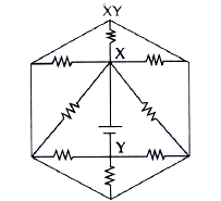 A64 mAB15 mAC9.8 mAD1 mA
In the circuit diagram shown in figure, potential difference across 3Ω resistance is 20 V. Then, match the following two columns.
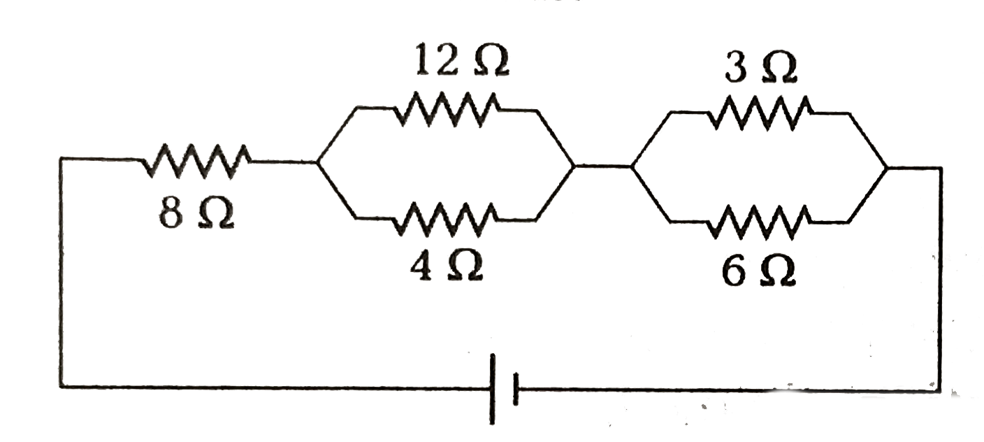
View SolutionIn the figure, the reverse breakdown voltage of a Zener diode is 5.6V, then the current IZ through the diode is
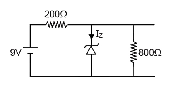
View SolutionIn the circuit shown in the figure , no current flows through the 8 Ω resistor, then the potential difference between points A and B(VA−VB)is
_PHY_E01_001_Q01.png)
View SolutionIn the circuit diagram shown in Figure, R=10Ω,L=l5H,E=20v,i=2A. This current is decreasing at a rate of −1.0A/s. Find Vab at this instant.

View SolutionIf the instantaneous change on the capacitor is 100μC and current through the circuit is decreasing at the rate of 2×10³ As then potential difference VA−VB is equal to
_PHY_E06_046_Q01.png)
View Solution

