The tuned circuit of an oscillator in a simple transimitter employs a coil and nanofarad () capacitor. If the oscillator ouput os modulated by audio frequency of , which of the following frequencies doesn't appear in the output ?
The correct Answer is:B
Step by step video, text & image solution for The tuned circuit of an oscillator in a simple AM transimitter employs a 40muH coil and 12 nanofarad (nF) capacitor. If the oscillator ouput os modulated by audio frequency of 5 kHz, which of the following frequencies doesn't appear in the output AM? by Physics experts to help you in doubts & scoring excellent marks in Class 12 exams.
Updated on:21/07/2023Topper's Solved these Questions
- COMMUNICATION SYSTEMBook:NARAYNAChapter:COMMUNICATION SYSTEMExercise:NCERT Based
Explore 16 Videos
- COMMUNICATION SYSTEMBook:NARAYNAChapter:COMMUNICATION SYSTEMExercise:Level-I(H.W)
Explore 11 Videos
- COMMUNICATION SYSTEMBook:NARAYNAChapter:COMMUNICATION SYSTEMExercise:Level-II(C.W)
Explore 34 Videos
- CAPACITANCEBook:NARAYNAChapter:CAPACITANCEExercise:Previous IIT-JEE
Explore 16 Videos
- CURRENT ELECTRICITYBook:NARAYNAChapter:CURRENT ELECTRICITYExercise:Level 6
Explore 43 Videos
Similar Questions
The tuned circuit the Oscillator in a simple AM transmitter employs a 50μH coil and a 1 nF capacitor. If the oscillator output is modulated by audio frequencies up to 10m kHz calculate the range occupied by the side bands.
View SolutionThe tuned circuit the Oscillator in a simple AM transmitter employs a 50μH coil and a 1 nF capacitor. If the oscillator output is modulated by audio frequencies up to 10m kHz calculate the range occupied by the side bands.
View Solution
Knowledge Check
The tuned circuit of an oscillator in a simple AM transimitter employs a 250 micro henry coil and 1nf condenser. If the oscillartor output is modulated by audio frequency upto 10KHz, the frequency range occupied by the side bands in KHz is
A210 to 230B258 to 278C308 to 328D118 to 128An LCR circuit is equivalent to a damped pendulum In an LCR circuit the capacitor is charged to Q0 and then connected to the L and R as shown below : Thus potential energy stored in the capacitor and that in the inductor also oscillates between maximum value an zero with double the frequency.
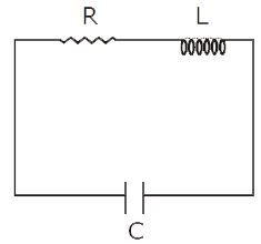
If a student plots graphs of the square of maximum charge (Q2max) on the capacitor with time (t) for two different values L1andL2(L1>L2) of L then which of the following reprersent this graph correctly ? (Plots are shematic and not drawn to scale )A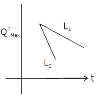 B
B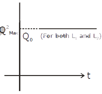 C
C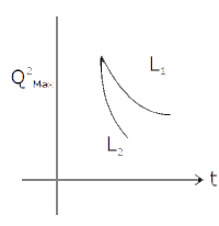 D
D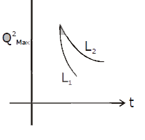
Read the following text and answer the following questions on the basis of the same:
Tuning a radio set: In essence the simplest tuned radio frequency receiver is a simple crystal set. Desired frequency is tuned by a tuned coil/ capacitor combination, and then the signal is presented to a simple crystal or diode detector where the amplitude modulated signal, is demodulated. This is then passed straight to the headphones or speaker. In radio set there is an LC oscillator comprising of a variable capacitor (or sometimes a variable coupling coil), with a knob on the front panel to tune the receiver.
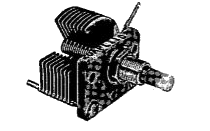
Capacitor used in old radio sets is gang capacitor. It consists of two sets of parallel circular plates one of which can rotate manually by means of a knob. The rotation causes overlapping areas of plates to change, thus changing its capacitance. Air gap between plates acts as dielectric.
The capacitor has to be tuned in tandem corresponding to the frequency of a station so that the LC combination of the radio set resonates at the frequency of the desired station.
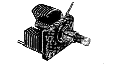
When capacitive reactance (XC) is equal to the inductive reactance (XL), then the resonance occurs 1 and the resonant frequency is given by ω0=1√LC current amplitude becomes maximum at the resonant frequency. It is important to note that resonance phenomenon is exhibited by a circuit only if both L and C are present in the circuit. Only then do the voltages across L and C cancel each other (both being out of phase) and the Current amplitude is open, VmR, the total source voltage appearing across R.
This means that we cannot have resonance in a RL or RC circuit.
Capacitor used in radio set for tuning is a:Aparallel plate capacitorBspherical capacitorCpaper capacitorDelectrolytic capacitor
In a simple AM transmitter, the tuned circuit uses a coil of 40μH and a shunt capacitor of 1 n F. If the oscillator output is modulated by audio frequencies upto 5kHz, what is the frequency range occupied by side bands?
View SolutionThe carrier frequency of a transmitter is provided by a tank circuit of a coil of inductance 49 μH and a capacitance of 2.5 nF It is modulated by an audio signal of 12 kHz The frequency range occupied by the side bands is :
View SolutionRead the following text and answer the following questions on the basis of the same:
Tuning a radio set: In essence the simplest tuned radio frequency receiver is a simple crystal set. Desired frequency is tuned by a tuned coil/ capacitor combination, and then the signal is presented to a simple crystal or diode detector where the amplitude modulated signal, is demodulated. This is then passed straight to the headphones or speaker. In radio set there is an LC oscillator comprising of a variable capacitor (or sometimes a variable coupling coil), with a knob on the front panel to tune the receiver.
Capacitor used in old radio sets is gang capacitor. It consists of two sets of parallel circular plates one of which can rotate manually by means of a knob. The rotation causes overlapping areas of plates to change, thus changing its capacitance. Air gap between plates acts as dielectric.
The capacitor has to be tuned in tandem corresponding to the frequency of a station so that the LC combination of the radio set resonates at the frequency of the desired station.
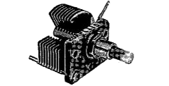
When capacitive reactance (XC) is equal to the inductive reactance (XL), then the resonance occurs 1 and the resonant frequency is given by ω0=1√LC current amplitude becomes maximum at the resonant frequency. It is important to note that resonance phenomenon is exhibited by a circuit only if both L and C are present in the circuit. Only then do the voltages across L and C cancel each other (both being out of phase) and the Current amplitude is open, VmR, the total source voltage appearing across R.
This means that we cannot have resonance in a RL or RC circuit.
Resonance frequency is equal to:
View SolutionRead the following text and answer the following questions on the basis of the same:
Tuning a radio set: In essence the simplest tuned radio frequency receiver is a simple crystal set. Desired frequency is tuned by a tuned coil/ capacitor combination, and then the signal is presented to a simple crystal or diode detector where the amplitude modulated signal, is demodulated. This is then passed straight to the headphones or speaker. In radio set there is an LC oscillator comprising of a variable capacitor (or sometimes a variable coupling coil), with a knob on the front panel to tune the receiver.
Capacitor used in old radio sets is gang capacitor. It consists of two sets of parallel circular plates one of which can rotate manually by means of a knob. The rotation causes overlapping areas of plates to change, thus changing its capacitance. Air gap between plates acts as dielectric.
The capacitor has to be tuned in tandem corresponding to the frequency of a station so that the LC combination of the radio set resonates at the frequency of the desired station.
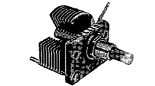
When capacitive reactance (XC) is equal to the inductive reactance (XL), then the resonance occurs 1 and the resonant frequency is given by ω0=1√LC current amplitude becomes maximum at the resonant frequency. It is important to note that resonance phenomenon is exhibited by a circuit only if both L and C are present in the circuit. Only then do the voltages across L and C cancel each other (both being out of phase) and the Current amplitude is open, VmR, the total source voltage appearing across R.
This means that we cannot have resonance in a RL or RC circuit.
Name the phenomenon involved in tuning a radio set to a particular radio station.
View SolutionRead the following text and answer the following questions on the basis of the same:
Tuning a radio set: In essence the simplest tuned radio frequency receiver is a simple crystal set. Desired frequency is tuned by a tuned coil/ capacitor combination, and then the signal is presented to a simple crystal or diode detector where the amplitude modulated signal, is demodulated. This is then passed straight to the headphones or speaker. In radio set there is an LC oscillator comprising of a variable capacitor (or sometimes a variable coupling coil), with a knob on the front panel to tune the receiver.
Capacitor used in old radio sets is gang capacitor. It consists of two sets of parallel circular plates one of which can rotate manually by means of a knob. The rotation causes overlapping areas of plates to change, thus changing its capacitance. Air gap between plates acts as dielectric.
The capacitor has to be tuned in tandem corresponding to the frequency of a station so that the LC combination of the radio set resonates at the frequency of the desired station.
When capacitive reactance (XC) is equal to the inductive reactance (XL), then the resonance occurs 1 and the resonant frequency is given by ω0=1√LC current amplitude becomes maximum at the resonant frequency. It is important to note that resonance phenomenon is exhibited by a circuit only if both L and C are present in the circuit. Only then do the voltages across L and C cancel each other (both being out of phase) and the Current amplitude is open, VmR, the total source voltage appearing across R.
This means that we cannot have resonance in a RL or RC circuit.
Resonance may occur in:
View Solution

