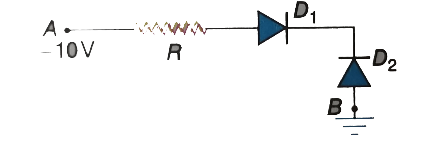
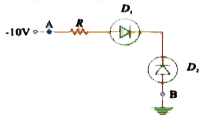
In Fig 1.50 assuming the diodes to be ideal
 Solution in Bengali
D1 is forward biased and D2 is reverse biased hence current flows from A to B
D2 is forward biased and D1 is reverse biased hence no current flows from B to A and vice versa
D1 and D2 are both forward biased and hence current flows A to B
D1 and D2 are both reverse biased and hence no current flows from A to B and vice versa
The correct Answer is:B
Step by step video & image solution for In Fig 1.50 assuming the diodes to be ideal by Physics experts to help you in doubts & scoring excellent marks in Class 12 exams.
Updated on:21/07/2023Topper's Solved these Questions
- SEMICONDUCTORS AND ELECTRONICS Book:CHHAYA PUBLICATIONChapter:SEMICONDUCTORS AND ELECTRONICS Exercise:NCERT EXEMPLAR QUESTIONS WITH ANSWER HINT (Multiple Options Correct )
Explore 1 Video
- SEMICONDUCTORS AND ELECTRONICS Book:CHHAYA PUBLICATIONChapter:SEMICONDUCTORS AND ELECTRONICS Exercise:EXERCISE (Multiple Choice Questions )
Explore 21 Videos
- SEMICONDUCTORS AND ELECTRONICS Book:CHHAYA PUBLICATIONChapter:SEMICONDUCTORS AND ELECTRONICS Exercise:NCERT TEXTBOOK QUESTIONS WITH ANSWER HINT
Explore 9 Videos
- REFRACTION OF LIGHTBook:CHHAYA PUBLICATIONChapter:REFRACTION OF LIGHTExercise:CBSE SCANNER
Explore 11 Videos
Similar Questions
Consider an n-p-n transistor with its base -emitter junction forward biased and collector -base junction reverse biased. Which of the following statements are true ?
View SolutionIf potential difference is applied the value of electric current
View SolutionIn an n-type silicon, which of the following statements is true?
View SolutionFor the same angle of incidence, the angles of refraction in three different media A, B and C are15∘,25∘ and 35∘ respectively. In which medium, will the velocity of light be minimum ?
View SolutionIn figure , assuming the diodes to be ideal ,
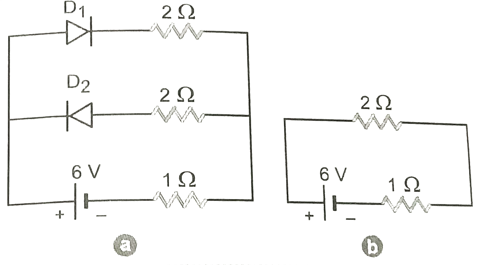
View SolutionFor the circuit shown in Fig., find the current flowing through the 1Ω resistor. Assume that the two diode are ideal diode.
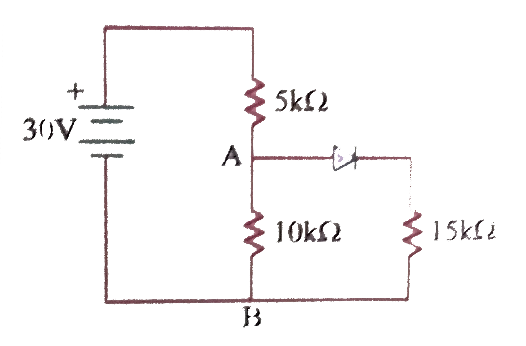
View SolutionFind the maximum voltage across AB in the circuit shown in Fig. Assume that diode is ideal.
 .
.
View SolutionAssuming that the junction diode is ideal the current through the diode is :-
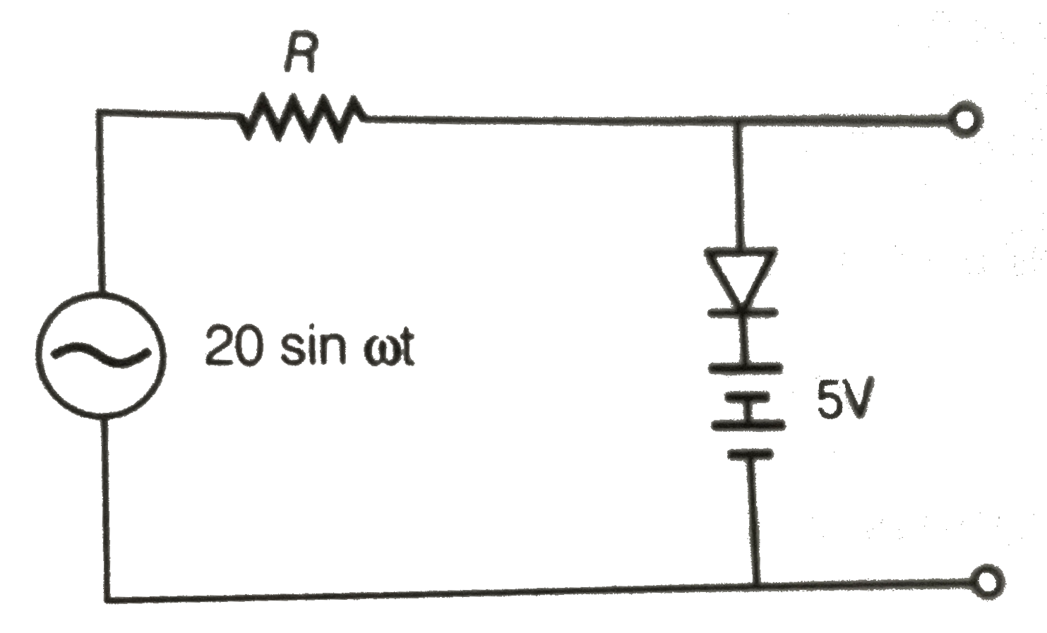
View SolutionAssuming the ideal diode, draw the output waveform for the circuit given in fig. (a), explain the waveform
View SolutionIn Fig assuming the diodes to be ideal :
View Solution" Four silicon diodes are connected as shows in fig Assuming the diodes to be ideal The current through the resister is "
View SolutionIn figure, assuming the diodes to be ideal,
View SolutionIn figure , assuming the diodes to be ideal ,
View SolutionIn figure , assuming the diodes to be ideal ,
View SolutionAssuming that the diode is an ideal diode, make the output waveform of the circuit in Fig. Explain this wave form.
View Solution

