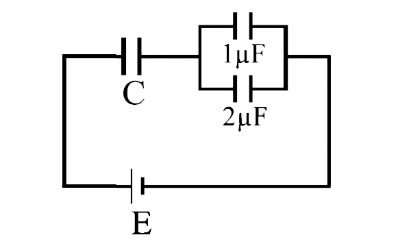
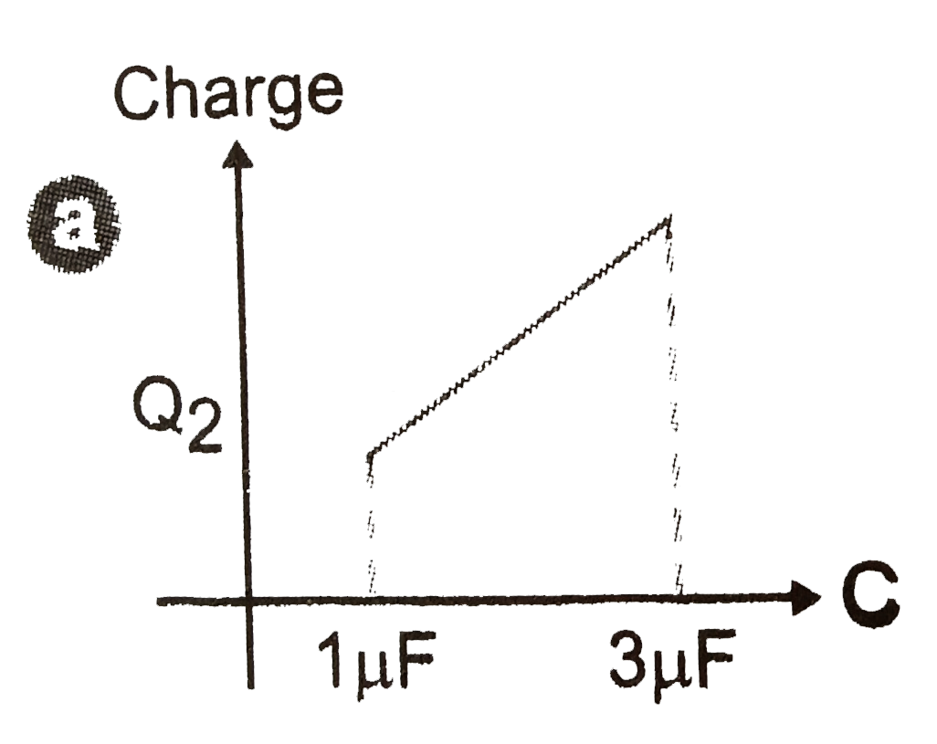
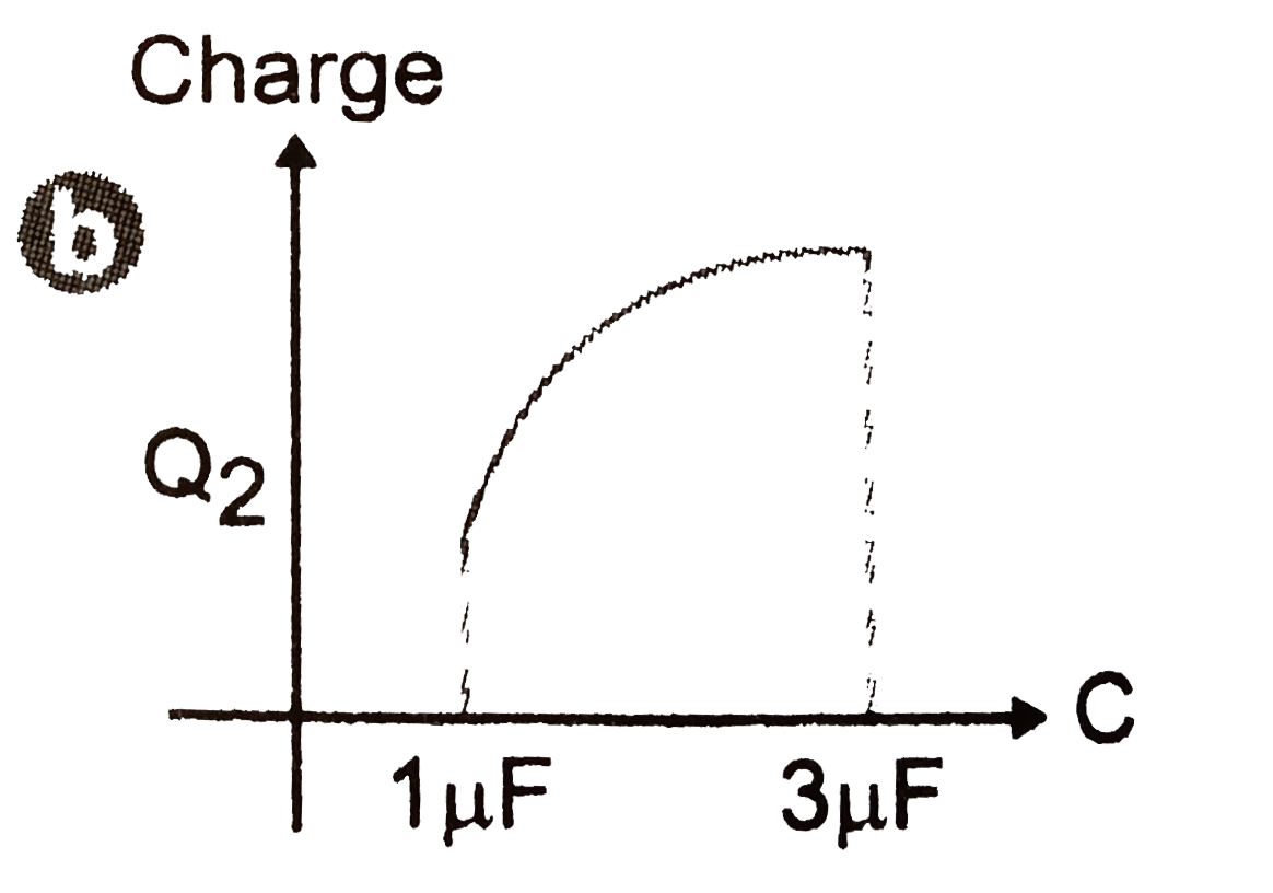
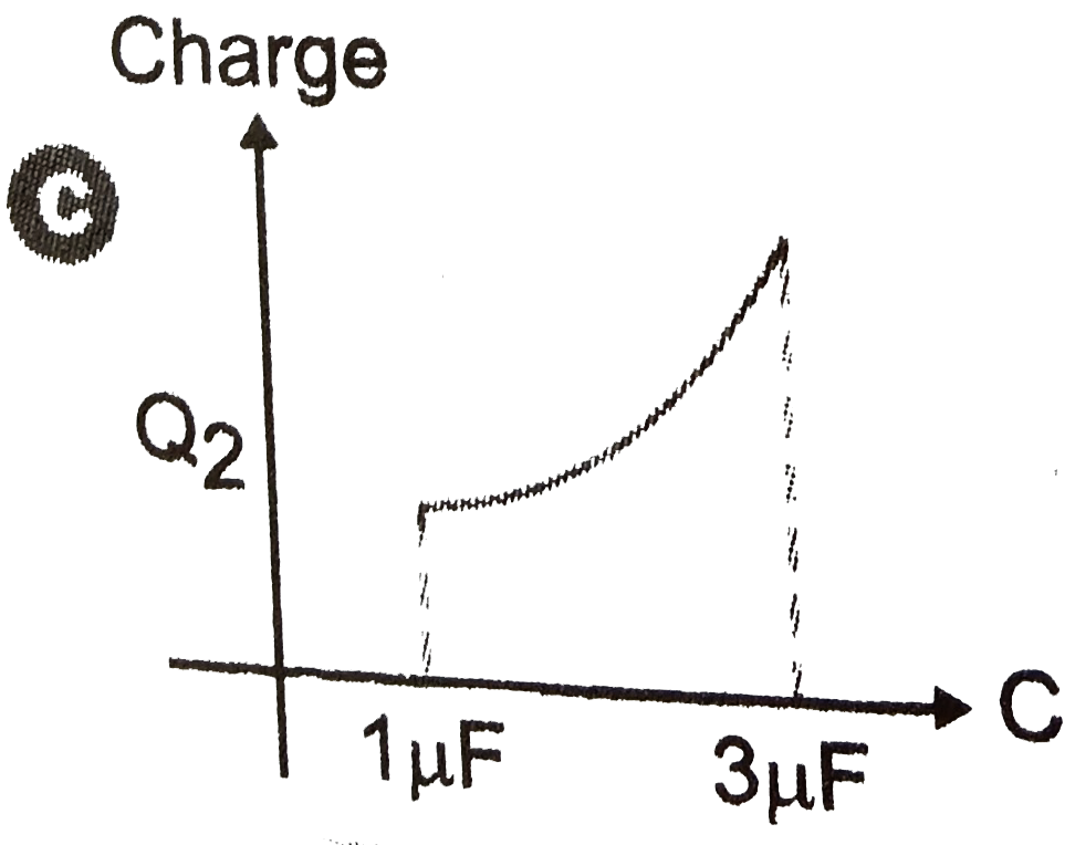
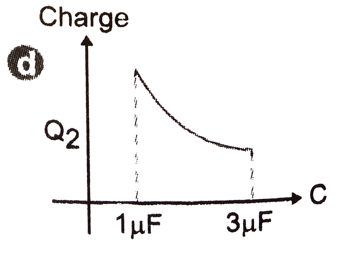
In the givven circuit, charge Q2 on the 2μF capacitor changes as C is varied from 1μF to 3μF. Q2 as a function of 'C' is given properly by: (figures are drawn schematically and are not to scale)
A
B
C
D
Video Solution
Text Solution
The correct Answer is:B
Here C1=1μF,C2=2μF,Cp=2+1=3μF
This combination is in series with C
∴Ceq=3C3+C
Total charge, q=CeqE=(3C3+C)E
Charge on 2μF capaicatance
q2=23×3CE3+C=2CE3+C=2E1+3C=Q, say
As dQdC>0.d2QdC2<0.
therefore Q2 versus C graph is shown correctly in Fig.
|
Topper's Solved these Questions
- ELECTROSTATICSBook:PRADEEPChapter:ELECTROSTATICSExercise:FILL IN THE BLANKS
Explore 8 Videos
- ELECTROSTATICSBook:PRADEEPChapter:ELECTROSTATICSExercise:PROBLEMS FOR PRACTICE
Explore 8 Videos
- ELECTROSTATICSBook:PRADEEPChapter:ELECTROSTATICSExercise:VALUE BASED QUESTIONS
Explore 7 Videos
- ELECTRONIC DEVICESBook:PRADEEPChapter:ELECTRONIC DEVICESExercise:Fill in the Blanks
Explore 1 Video
- MAGNETIC EFFECT OF CURRENT AND MAGNETISMBook:PRADEEPChapter:MAGNETIC EFFECT OF CURRENT AND MAGNETISMExercise:Competition Focus (Multiple Choice Questions)
Explore 2 Videos
Similar Questions
Knowledge Check
In the circuit shown in figure, charge on 10μF capacitor is given as
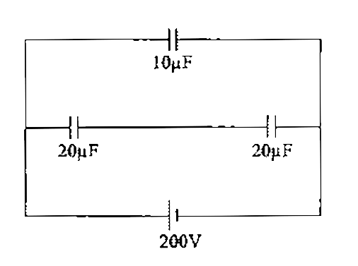 A2×10−3CB16×10−4CC4×10−3CD8×10−4C
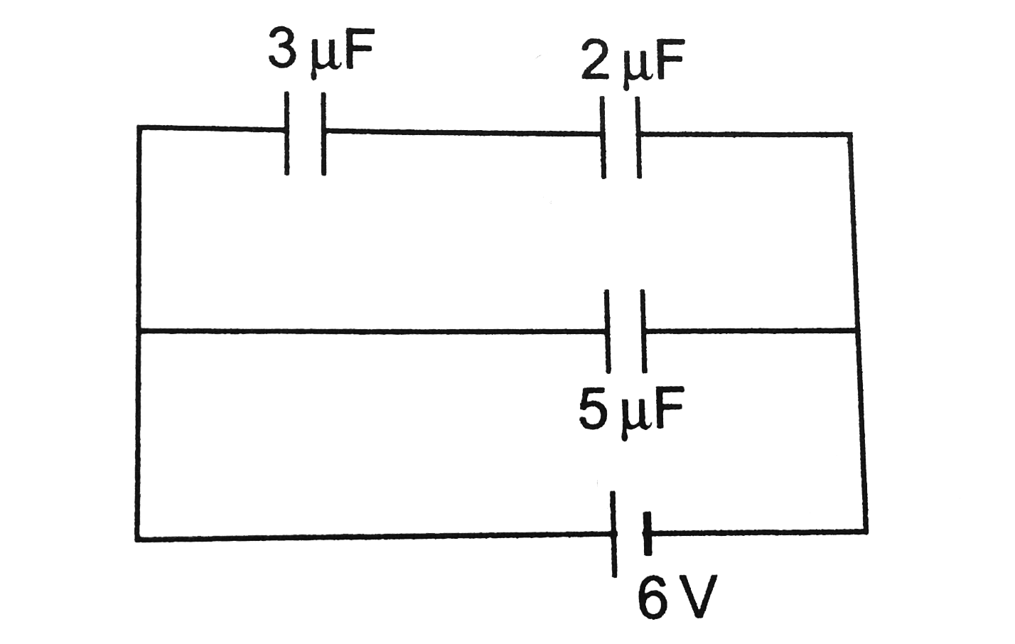
In the circuit shown in figure charge stored in the capacitor of capacity 5μF is
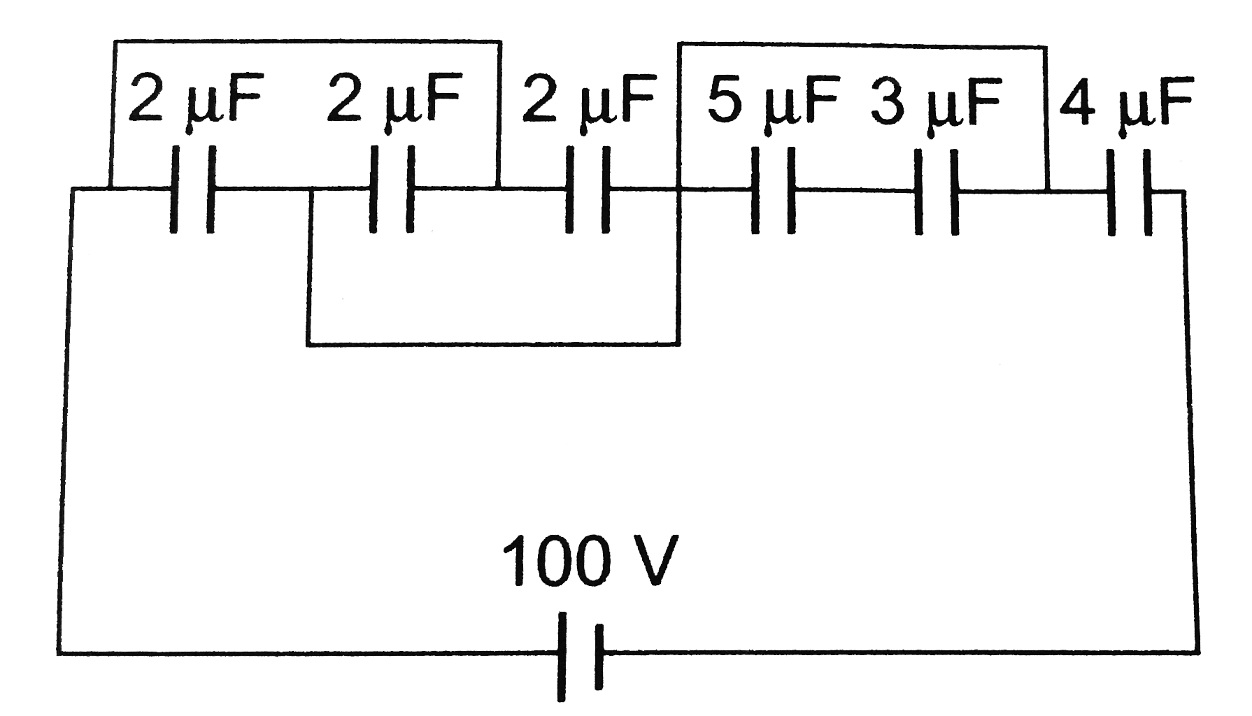 A60μCB20μCC30μCDzero
In the circuit shown in, C=6μF. The charge stored in the capacitor of capacity C is
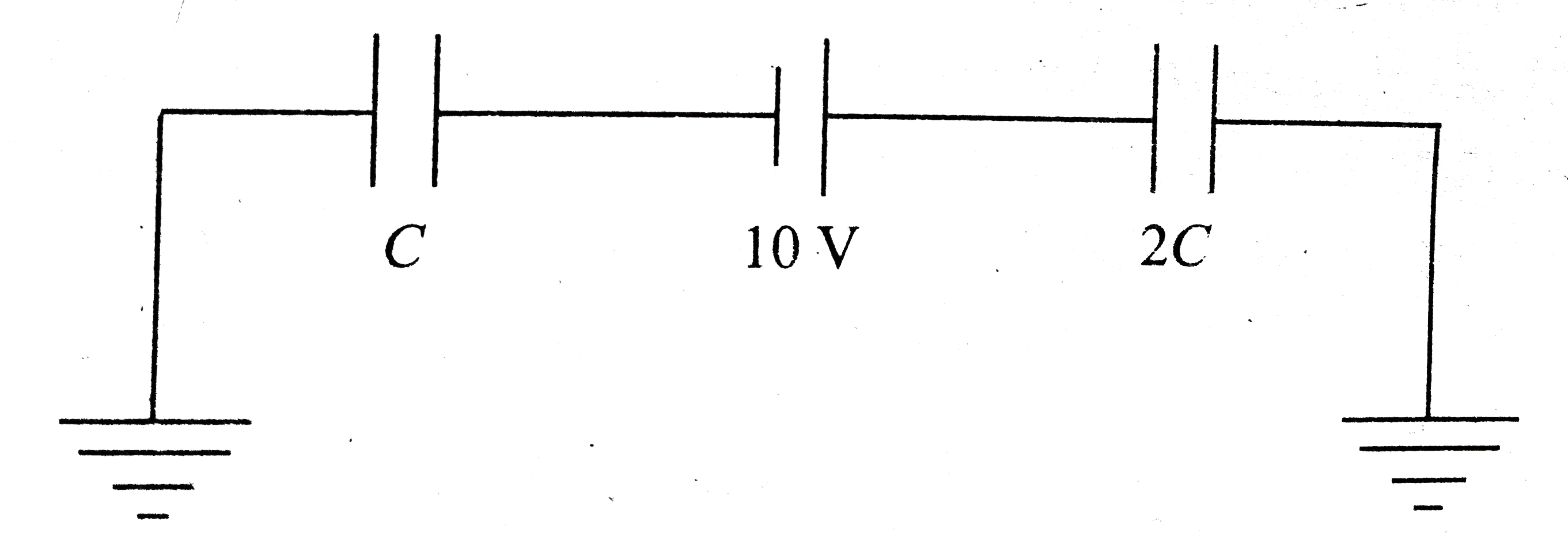 . AzeroB90μCC40μCD60μC
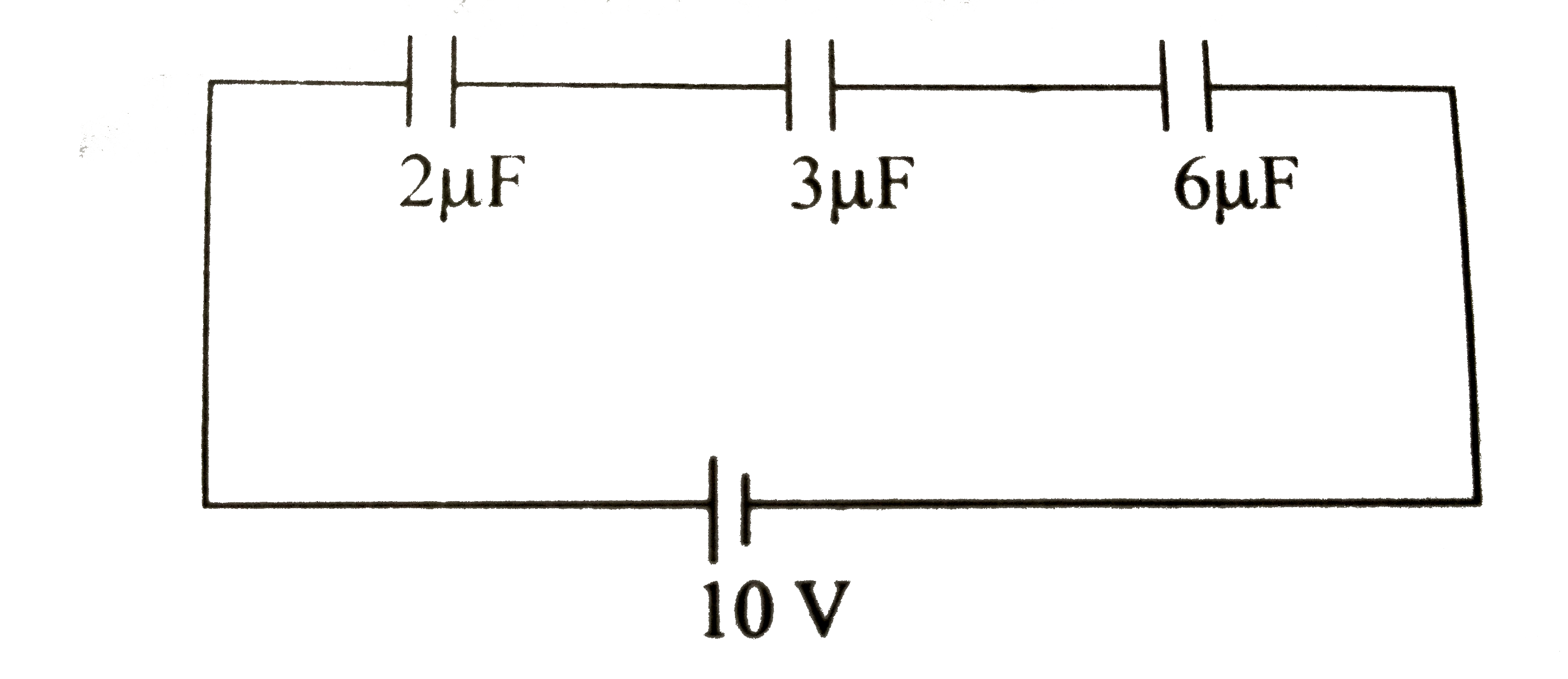
The charge on 3μF capacitor shown in the figure is
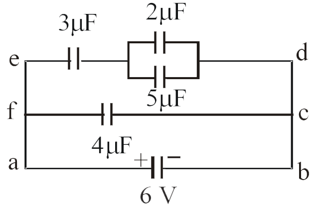
View SolutionIn the circuit given below, the charge in μC, on the capacitor having 5μF is
View SolutionFor the circuit shown in figure the charge on 4μF capacitor is

View SolutionIn the circuit shown in figure, the ratio of charge on 5μF and 2μF capacitor is
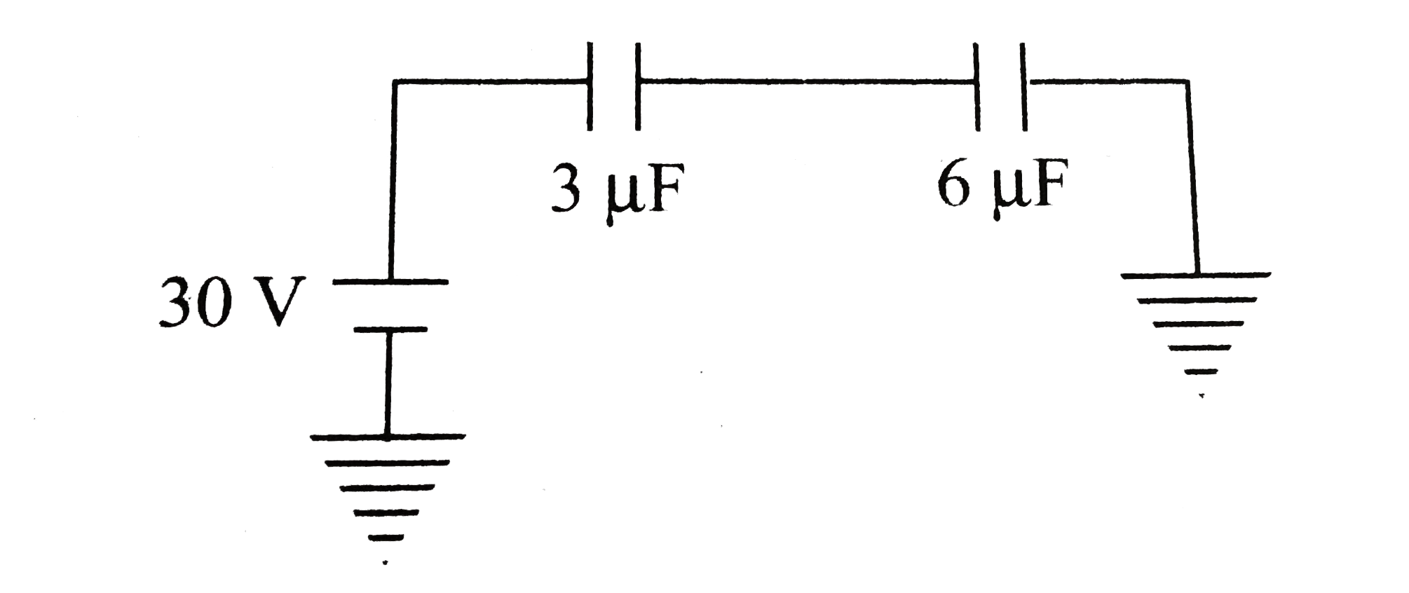
View SolutionIn the circuit shown in figure, the charge stored on a capacitor of capacitance 3μF is
View Solution


