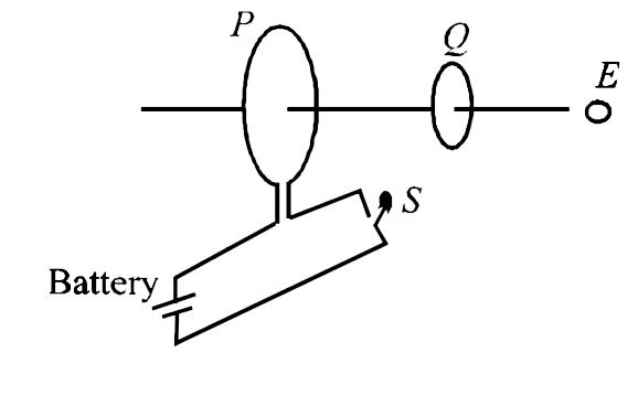
As shown in the figure, P and Q are two coaxial conducting loops separated by some distance. When the switch S is closed, a clockwise current IP (as seen by E) and an induced current IQ1 flows in Q. The switch remains closed for a long time. when S is opened, a current IQ2 flows in Q. Then the direction IQ1andIQ2 (as seen by E) are
A
respectively clockwise and anti-clockwise
B
both clockwise
C
both anti-clockwise
D
respectively anti-clockwise and clockwise
Video Solution
Text Solution
The correct Answer is:D
Let the switch be closed at time t=0. The current Op flowing in P grows for a time, say t0, after which it becomes steady. During this time the magnetic field (du to Ip) (from left to right) increases at the location of loop Q. According to Lenz's law, the induced current (IQ)1 should be such that it tries to decrease the magnetic field. Therefore, the magnetic field due to this current must be from right to left. Hence this induced current (IQ)1 should be anticlockwise (opposite to the direction of Ip). After the switch S is opened, the current IP takes a finite time to decay to zero and the reverse of the above phenomenon is observed. Hence the induced current (IQ)2 should be clockwise.
|
Similar Questions
Knowledge Check
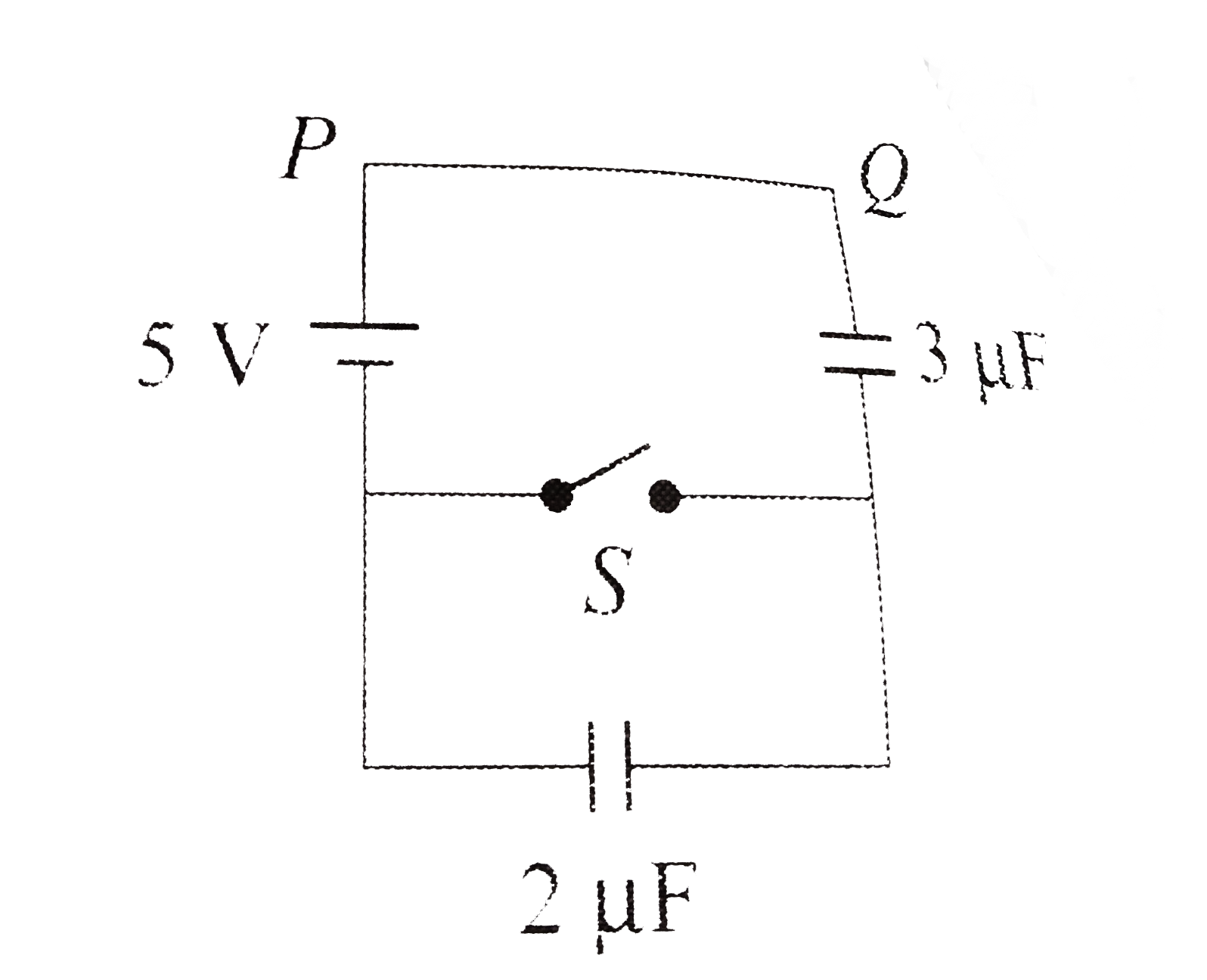
In fig. A2.27, the charge that flows from P to Q when the switch S is closed is
 A3μCB6μCC9μCD15μC
In the circuit shown, the switch is closed at t=0, the currents I1,I2 and I3 are
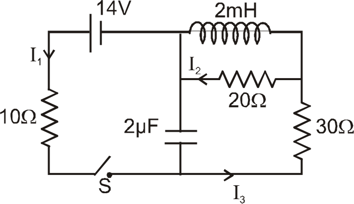 A1.4A,0,0B1.4 A,0.70 A,0.70 AC0,0,0D1.2A,0.6A,0.6A
In the circuit shown in the figure The steady state currents i1andi2 in the coils after the switch S is closed are
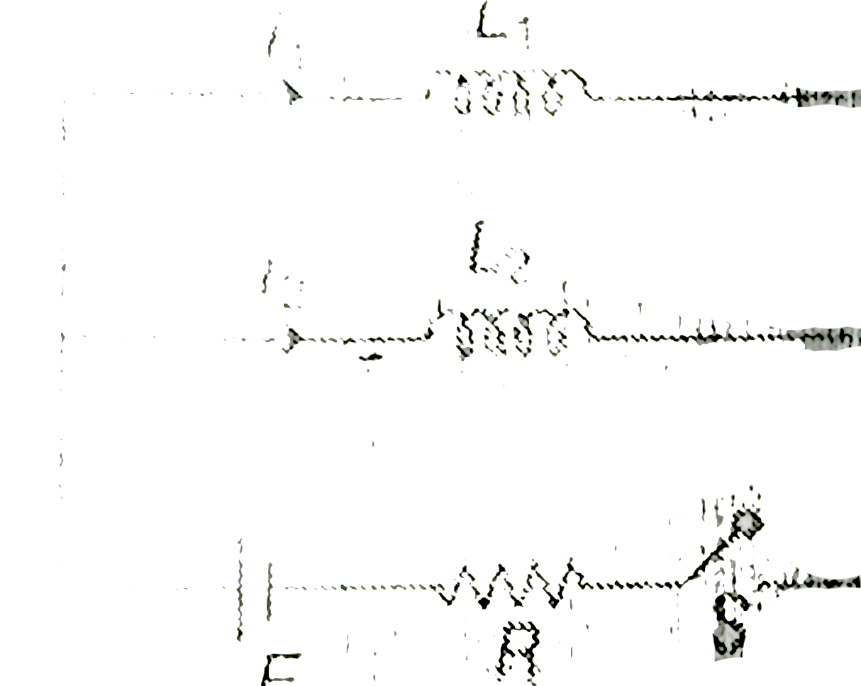 Ai1=EL2R(L1+L2)Bi1=EL1R(L1+L2)Ci2=EL2R(L1+L2)Di2=E√L1L2RL2
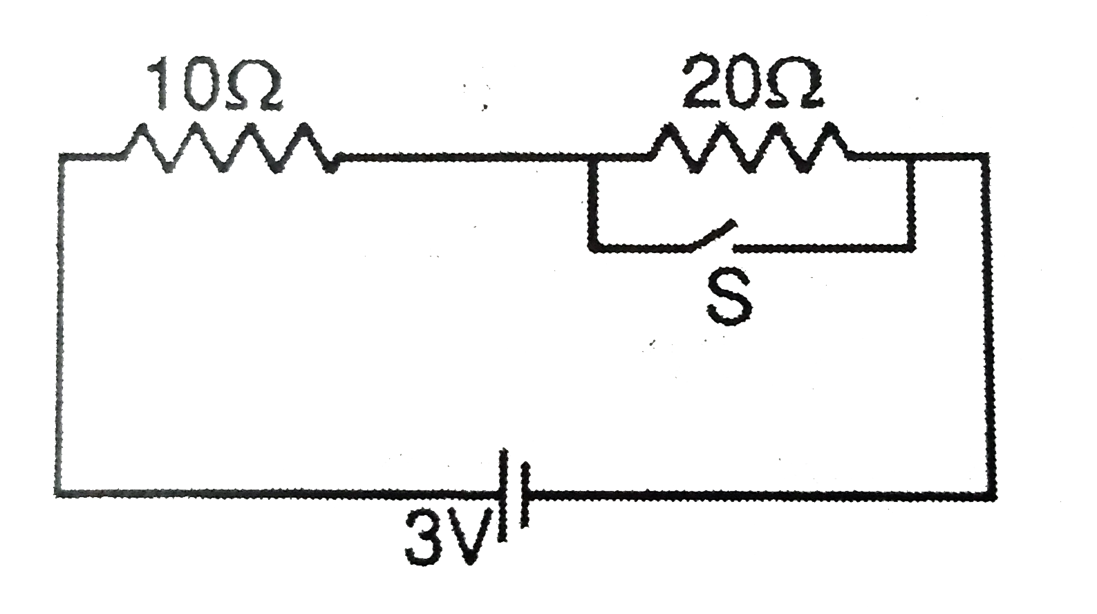
Consider the circuit shown in figure. Find the current through the 10Ω resistor when the switch S is (a) opened (b) closed.
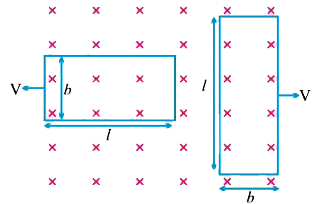
View SolutionIn the figure shown, coils P and Q are identical and moving apart with same velocity V. Induced currents in the coils are I1andI2. Find I1/I2.
View SolutionIn the circuit shown in figure switch S is closed at time t=0
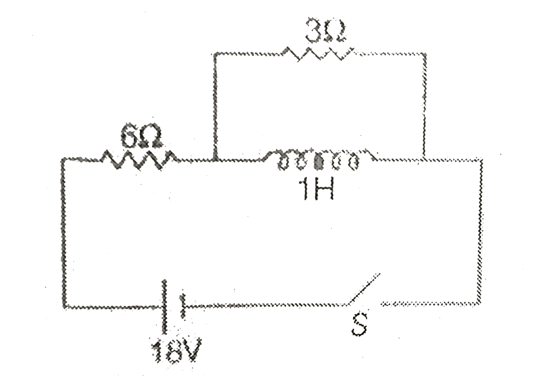
Current I from the battery at time t is given by
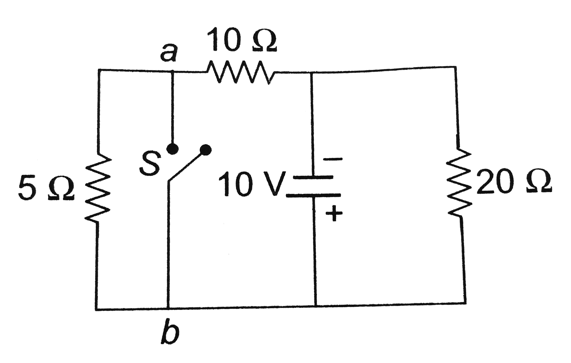
View SolutionIn the circuit shown below, the current that flows from a to b when switch S is closed is
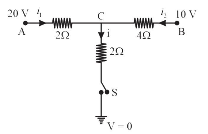
View SolutionWhen the switch S, in the circuit shown , is closed , then the Value of current i will be :
View Solution

