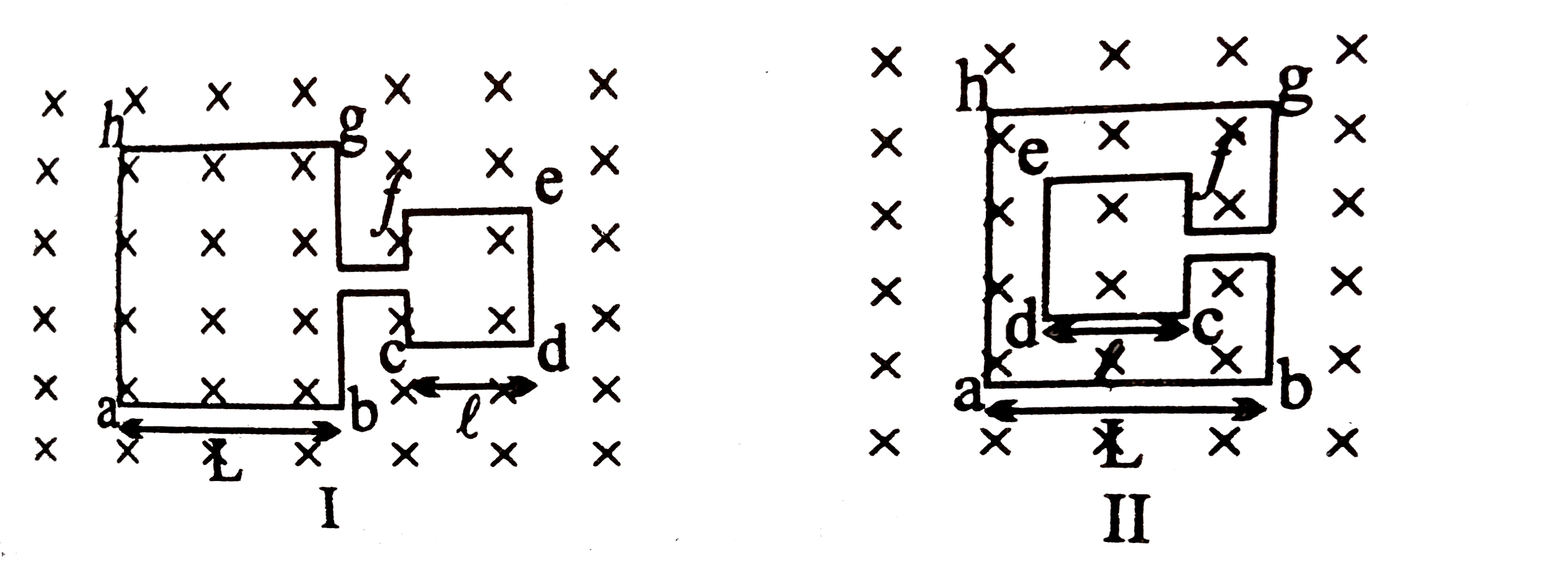
The adjoining figure shows two different arrangements in which two square wire frames of same resistance are placed in a uniform constantly decreasing magnetic field B.

If I1 and I2 are the magnetitudes of induced current in the cases I and II, respectively, then
I1=I2
I1>I2
I1<I2
nothing can be said
The correct Answer is:B
I1>I2 from result of Q.3.
Similar Questions
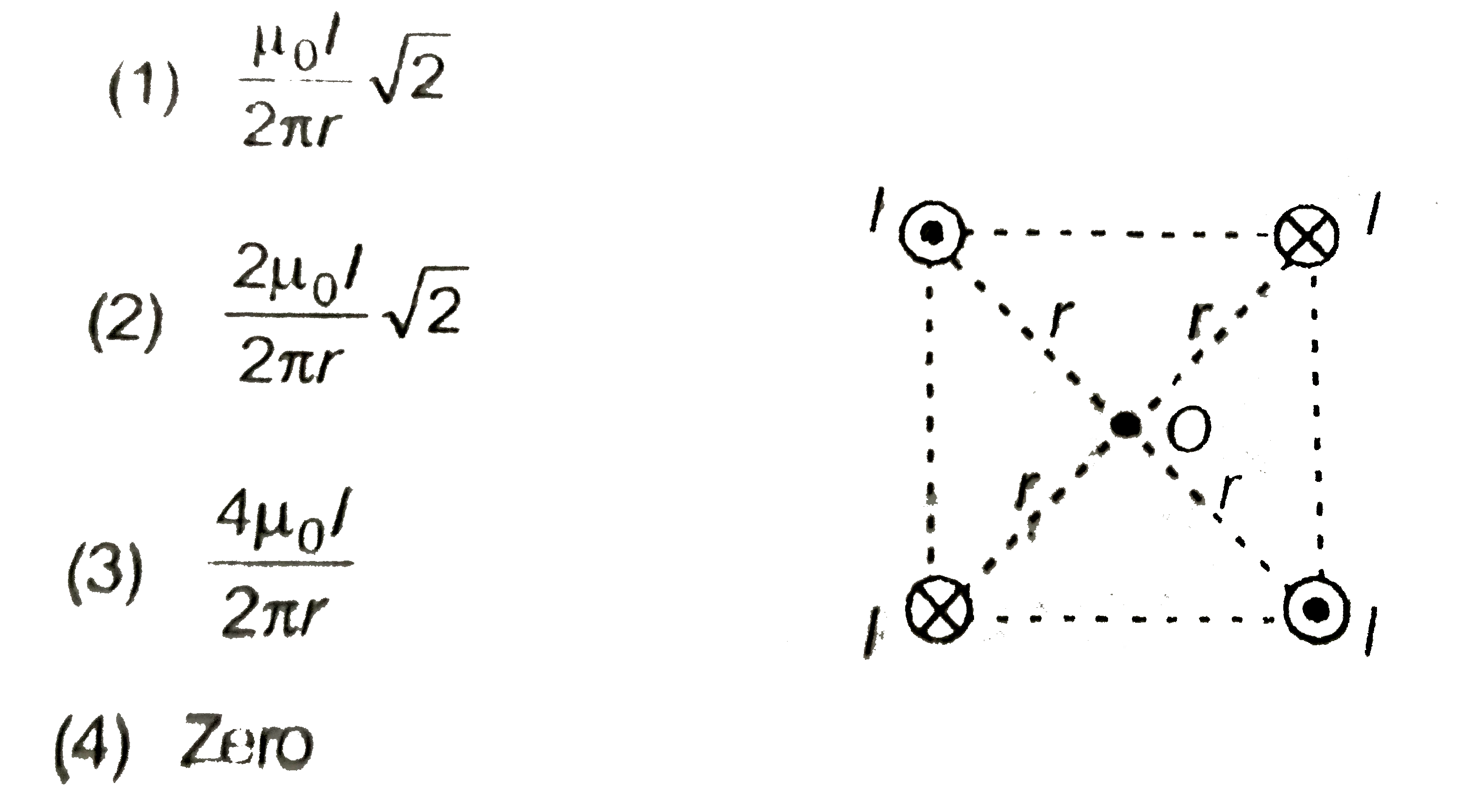
Figure shows an arrangement in which long parallel wires carrying equal currents into or out of the page of paper at the corners of a square. The magnetic field at the centre of square is

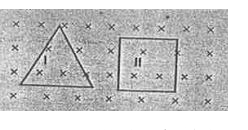
View SolutionTwo current carrying closed loops having equal perimeters are placed in a uniform magnetic field as. Shown in the figure. What is the ratio of magnitude of torque acting on the loop [loop I is equilateral triangle and loop II is square]

View Solution
Knowledge Check
The adjoining figure shows two different arrangements in which two square wire frames of same resistance are placed in a uniform constantly decreasing magnetic field B.

The direction of induced current in the case I isAfrom a to b and from c to dBfrom a to b and from f to eCfrom b to a and from d to cDfrom b to a and from e to fThe adjoining figure shows two different arrangements in which two square wire frames of same resistance are placed in a uniform constantly decreasing magnetic field B.

The direction of induced current in the case II isAfrom a to b and from c to dBfrom b to a and from f to eCfrom b to a and from c to dDfrom a to b and from d to cThe adjoining figure shows two different arrangements in which two square wire frames of same resistance are placed in a uniform constantly decreasing magnetic field B.

The value of magnetic flux in each case is given byACase I: Φ=π(L2+l2)B,
Case II: Φ=π(L2−l2)BBCase I: Φ=π(L2+l2)B,
Case II: Φ=π(L2+l2)BCCase I: Φ=(L2+l2)B,
Case II: Φ=(L2−l2)BDCase I: Φ=(L2+l2)B,
Case II: Φ=π(L2−l2)B
Two coils are having magnetic field B and 2B at their centres and current i and 2i then the ratio of their radius is
View SolutionTwo identical wires AandB , each of length 'l', carry the same current I. Wire A is bent into a circle of radius RandwireB is bent to form a square of side 'a' . If BAandBB are the values of magnetic field at the centres of the circle and square respectively , then the ratio BABB is :
View SolutionA circular flexible loop of wire of radius r carrying a current I is placed in a uniform magnetic field B . If B is doubled, then tension in the loop
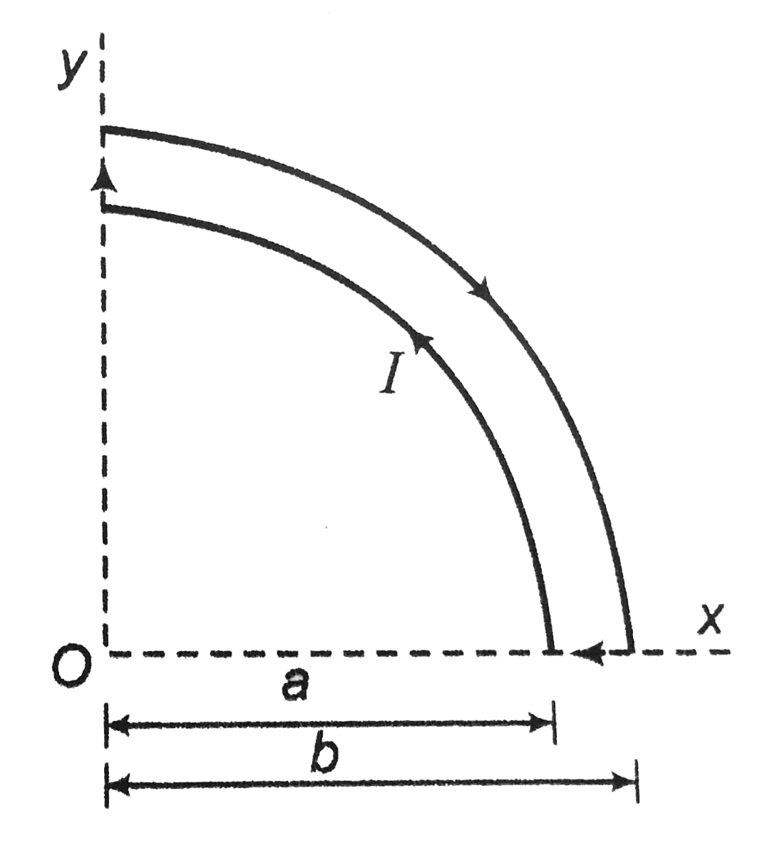
View SolutionThe figure shows a wire frame in xy-plane carrying current I. The magnetic field at the point O is

View SolutionTwo identical wires A and B have the same length l and carry the same current I. Wire A is bent into a circle of radius R and wire B is bent to form a square of side a. If B1andB2 are the values of magnetic induction at the centre of the circle and the centre of the square, respectively, then the ratio B1/B2 is
View Solution
