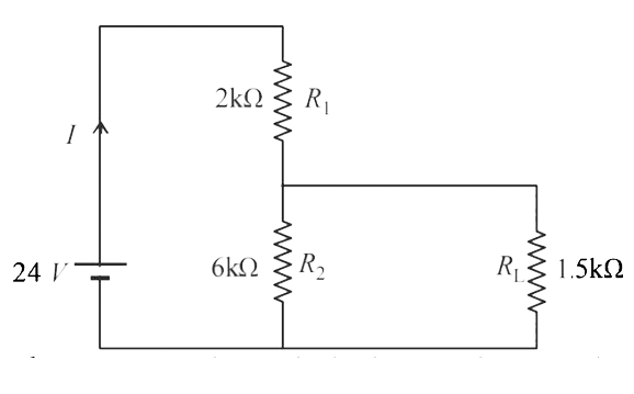
For the circuit shown in figure
A
the current I through the battery is 7.5mA
B
the potential difference across RL is 18V
C
ratio of powers dissipated in R1 and R2 is 3
D
if R1 and R2 are interchanged, magnitude of the power dissipated in RL will decreases by a factor 9
Video Solution
Text Solution
The correct Answer is:A, D
Req=2kΩ+(6kΩ∣∣1.5kΩ)
Req=3.2kΩ
(A) I=24V3.2kΩ⇒I=7.5mA
(B)VRL=1.23.2×24⇒VRL=9V
V1=24−9⇒V2=15 volt
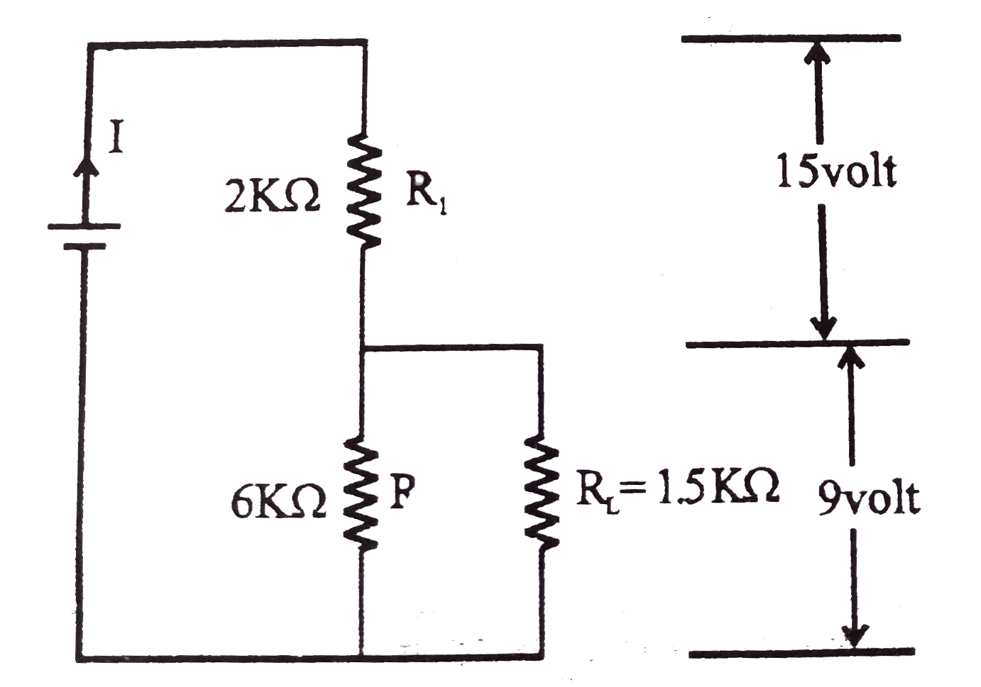
(C) PR1=(15)2(2×10³)=2252×103 Watt
PRL=(9)26×103=816 watt
(D) In first case
PRL=(9)21.5×10³
For second case
V'RL=(6/7)(6+6/7)×24V=3V
P'RL=(3)2(1.5×10³) Watt
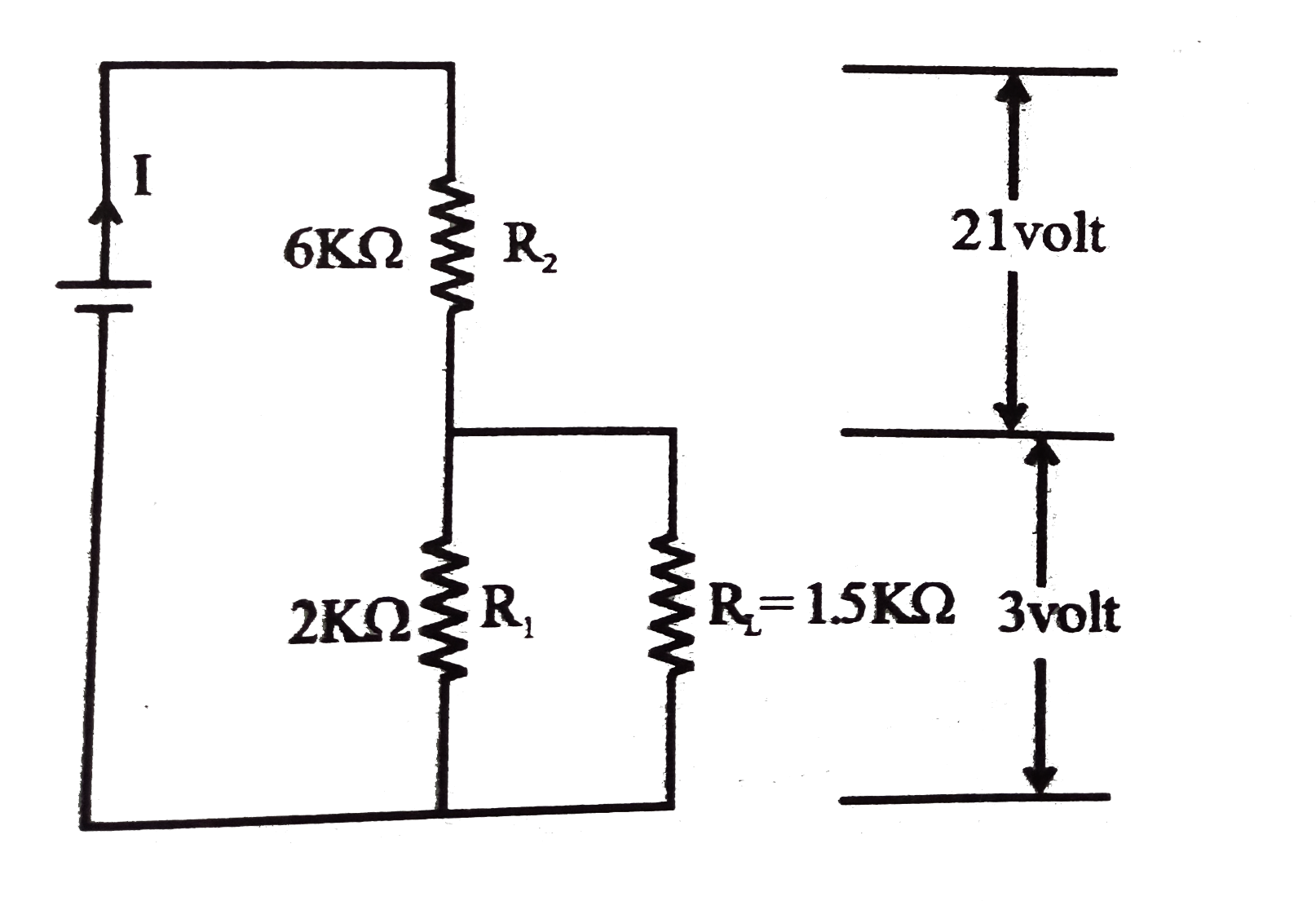
P'RL=19PRL
|
Similar Questions
Knowledge Check
In the circuit shown in figure
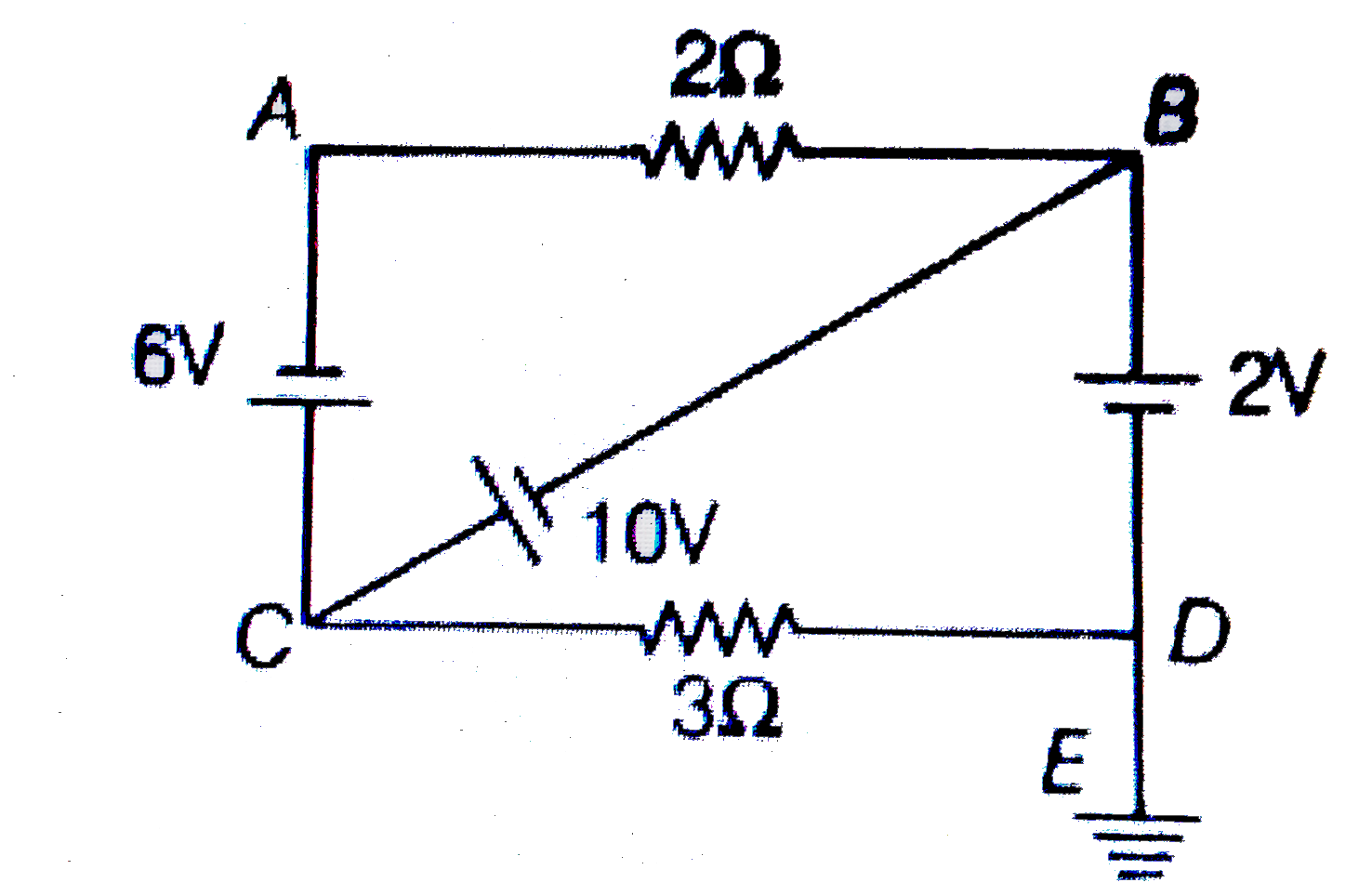 Acurrent passing through 2Ω resistance is 2 ABcurrent passing through 3Ω resistance is 4 ACcurrent in wire DE is zero.Dpotential of point A is 10 V
In the circuit shown in figure
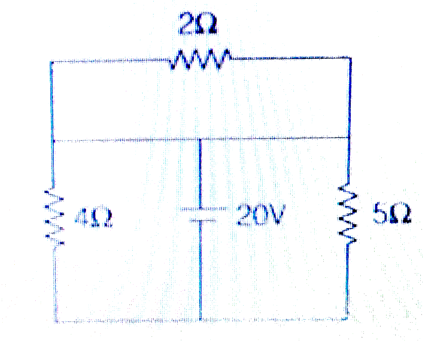 Acurrent passing through 2Ω resistance is zeroBcurrent passing through 4Ω resistance is 5 ACcurrent passing through 5Ω resistance is 4 ADAll of the above
In the circuit shown in figure
 AE = 6.6 VBi1=1.1ACi2=0.5ADE = 4.4 V

