A resistor circuit is constructed such that 12 resistor are arranged to form a cube as shown in fig. Each resistor has a resistance of 2Ω. The potential difference of 30V is applied across two of the opposing points as shown
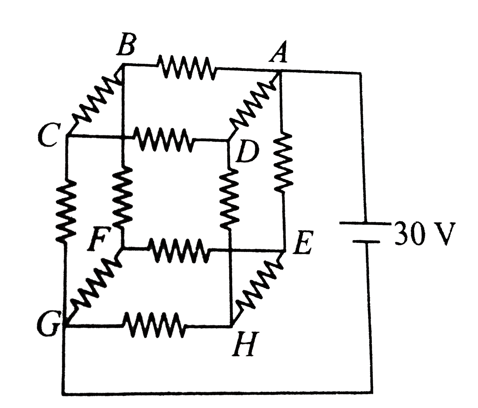
The points having the same potential are
i. B,D,E ,ii. C,F,H ,iii. C,E
The correct Answer is:D
Step by step video, text & image solution for A resistor circuit is constructed such that 12 resistor are arranged to form a cube as shown in fig. Each resistor has a resistance of 2Omega. The potential difference of 30V is applied across two of the opposing points as shown The points having the same potential are i. B,D,E ,ii. C,F,H ,iii. C,E by Physics experts to help you in doubts & scoring excellent marks in Class 12 exams.
Similar Questions
Two resistors of resistances 10Ω and 20Ω are joined in parallel. A potential difference of 12V is applied across the combination. Find the power consumed by each resistor.
View SolutionTwo resistors of resistances 10Ω and 20Ω are joined in series. A potential difference of 12V is applied across the combination. Find the power consumed by each resistor.
View Solution
Knowledge Check
- Question 1 - Select One
A resistor circuit is constructed such that 12 resistor are arranged to form a cube as shown in fig. Each resistor has a resistance of 2Ω. The potential difference of 30V is applied across two of the opposing points as shown
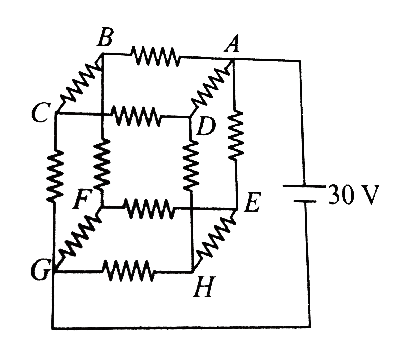
In question 20, the potential difference between the points C and G isA15VB10VC20VD7.5V - Question 2 - Select One
A resistor circuit is constructed such that 12 resistor are arranged to form a cube as shown in fig. Each resistor has a resistance of 2Ω. The potential difference of 30V is applied across two of the opposing points as shown
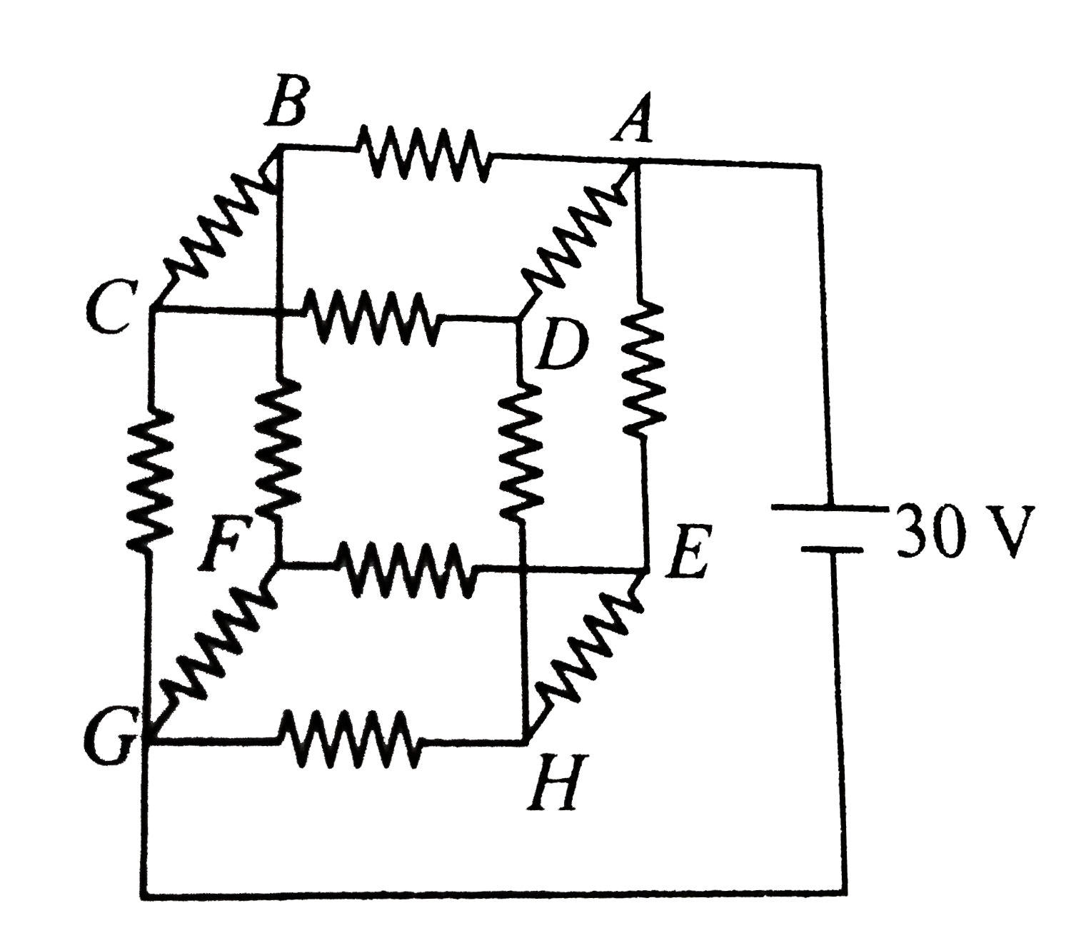
If we replace resistor between A and B and resistors between G and H by wires of zero resistance, then the points having the same potential are
i. D,E,C,F ,ii. A,B ,iii. G,HAOnly (i) is correct.BOnly (ii) is correct.COnly (iii) is correct.D(i), (ii) and (iii) are correct.
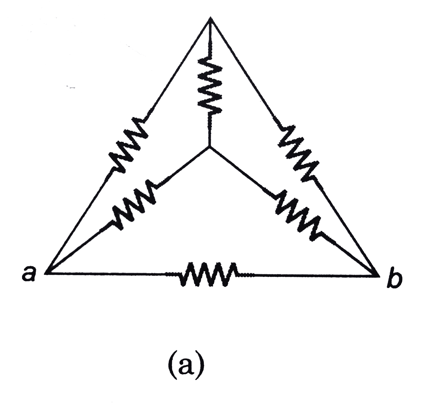
Find the equivalent resistance of the circuits shown in figure between the points a and b. Each resistor has a resistance r.
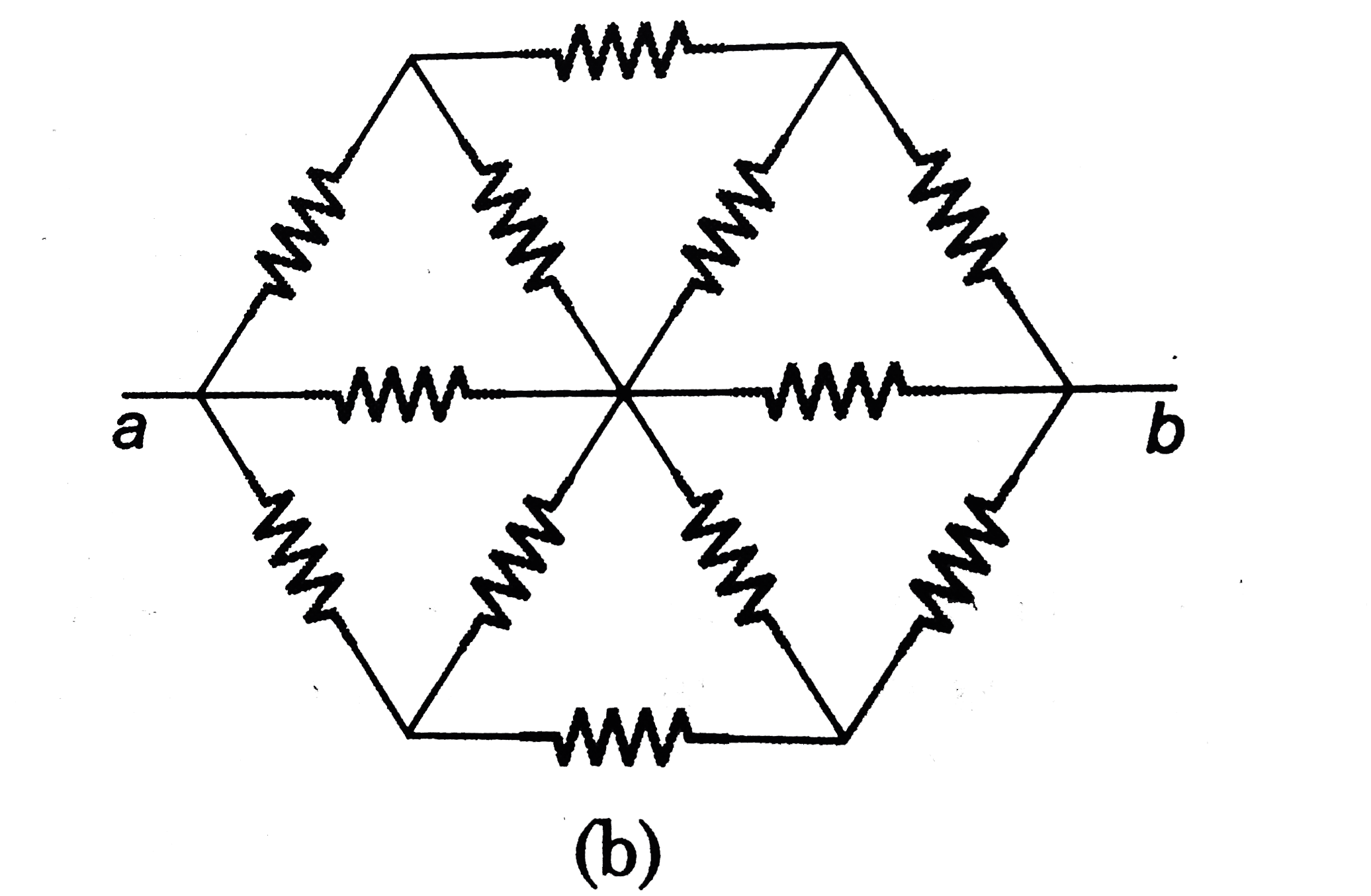 View Solution
Find the equivalent resistance of the circuit shown in figure between the points a and b.Each resistor has a resistances r.
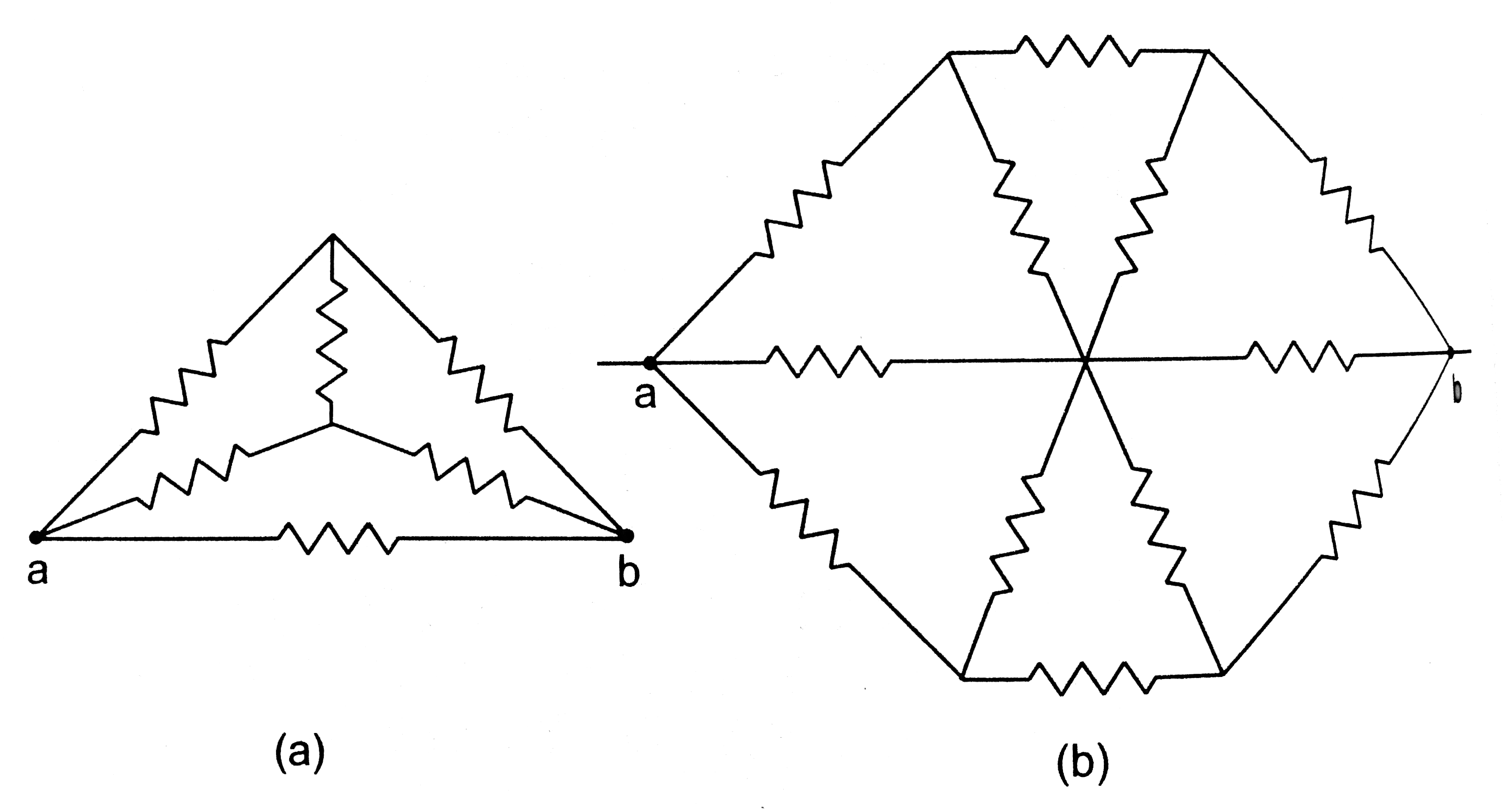 View Solution
In the circuit shown in Fig. 4.41, calculate the current in each resistor and potential difference across each resistor.
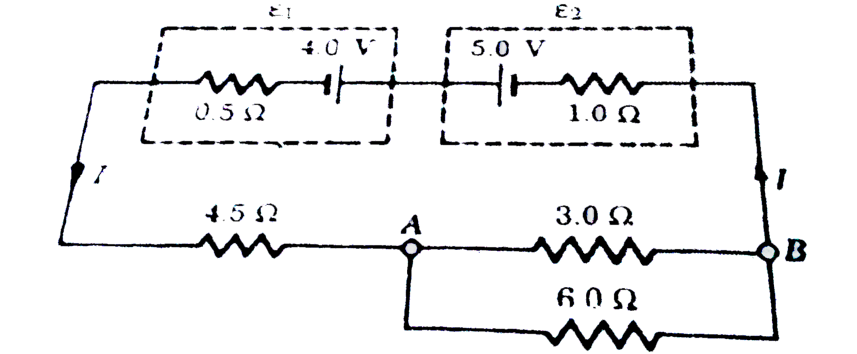 View Solution
Find the equivalent resistance of the circuit shown in Fig.4.60 between the points A and B. Each resistor has a resistance r.
 View Solution
Calculate the current 10Ω and 20Ω are joined in series. A potential difference of 12 V is applied across the combination. Find the power consumed by each resistor.
View SolutionEach of the resistors shown in figure has a resistances of 10(Ω)and each of the batteries has an emf of 10V.Find the currents through the resistors a and b in the two circuits.
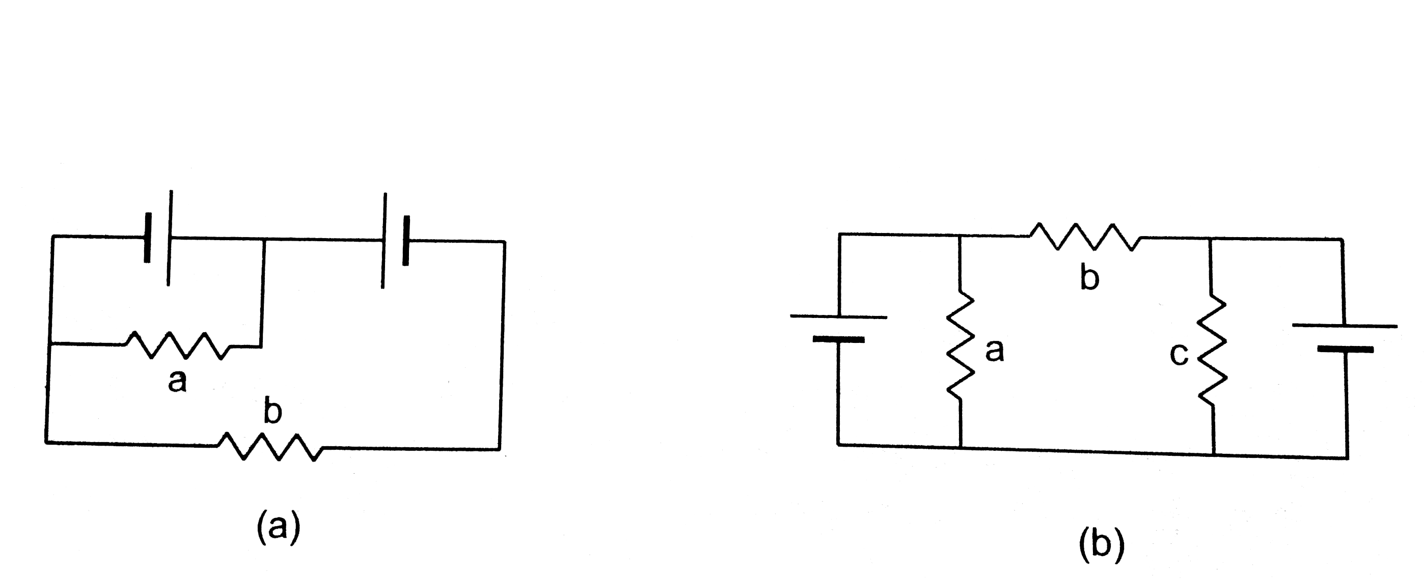 View Solution

