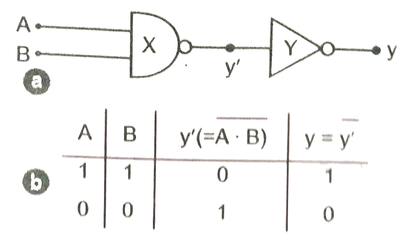
Identify the logic gates marked X,Y in Fig. MTP 1.1. write down the output at y, when A=1,B=1 and A=0 and B=0.

X is NOR gate and Y is NOT gate: (1,0).
Topper's Solved these Questions
- COMMUNICATION SYSTEMSBook:PRADEEPChapter:COMMUNICATION SYSTEMSExercise:Multiple choice questions
Explore 3 Videos
- COMMUNICATION SYSTEMSBook:PRADEEPChapter:COMMUNICATION SYSTEMSExercise:Multiple Choice Question
Explore 4 Videos
- COMMUNICATION SYSTEMSBook:PRADEEPChapter:COMMUNICATION SYSTEMSExercise:Value Based Questions
Explore 4 Videos
- ATOMS AND NUCLEIBook:PRADEEPChapter:ATOMS AND NUCLEIExercise:Assertion- Reason type question 12
Explore 1 Video
- CURRENT ELECTRICITYBook:PRADEEPChapter:CURRENT ELECTRICITYExercise:Problems for Practice (B)
Explore 2 Videos
Similar Questions
Knowledge Check
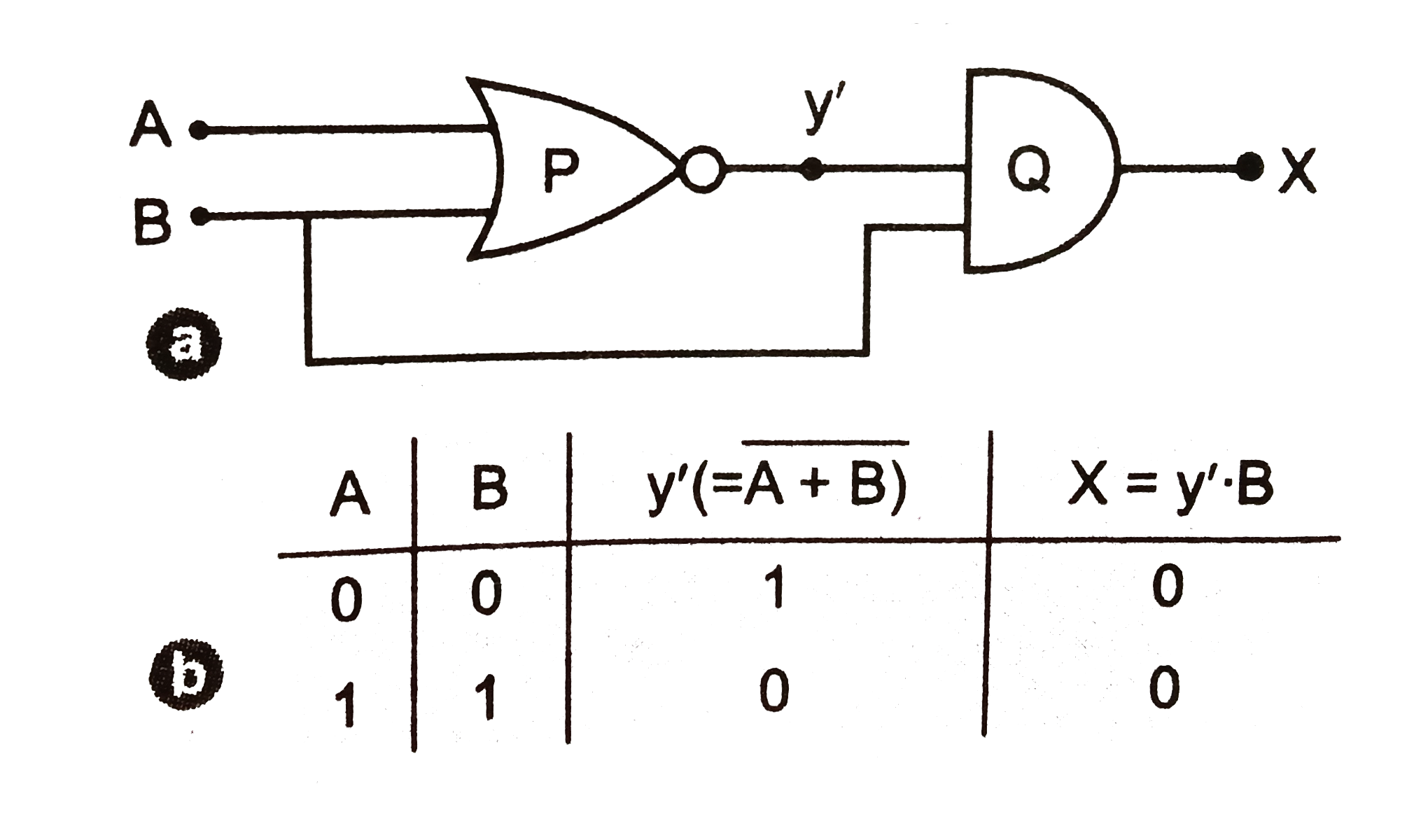
Write down the output at X for the inputs A = 0 , B = 0 and A = 1 , B = 1
 Ax = 0 and 0Bx = 0 and 1Cx = 1 and 0Dx = 1 and 1
Write down the output at X for the inputs A = 0, B = 0 and A = 1, B = 1
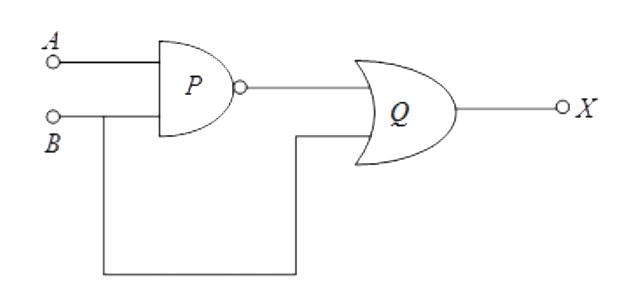
View SolutionIdentify the logic gates marked P and Q in the given logic circuit Fig. Write down then output at X for the inputs
(i) A=0,B=0 and (ii) A=1,B=1.
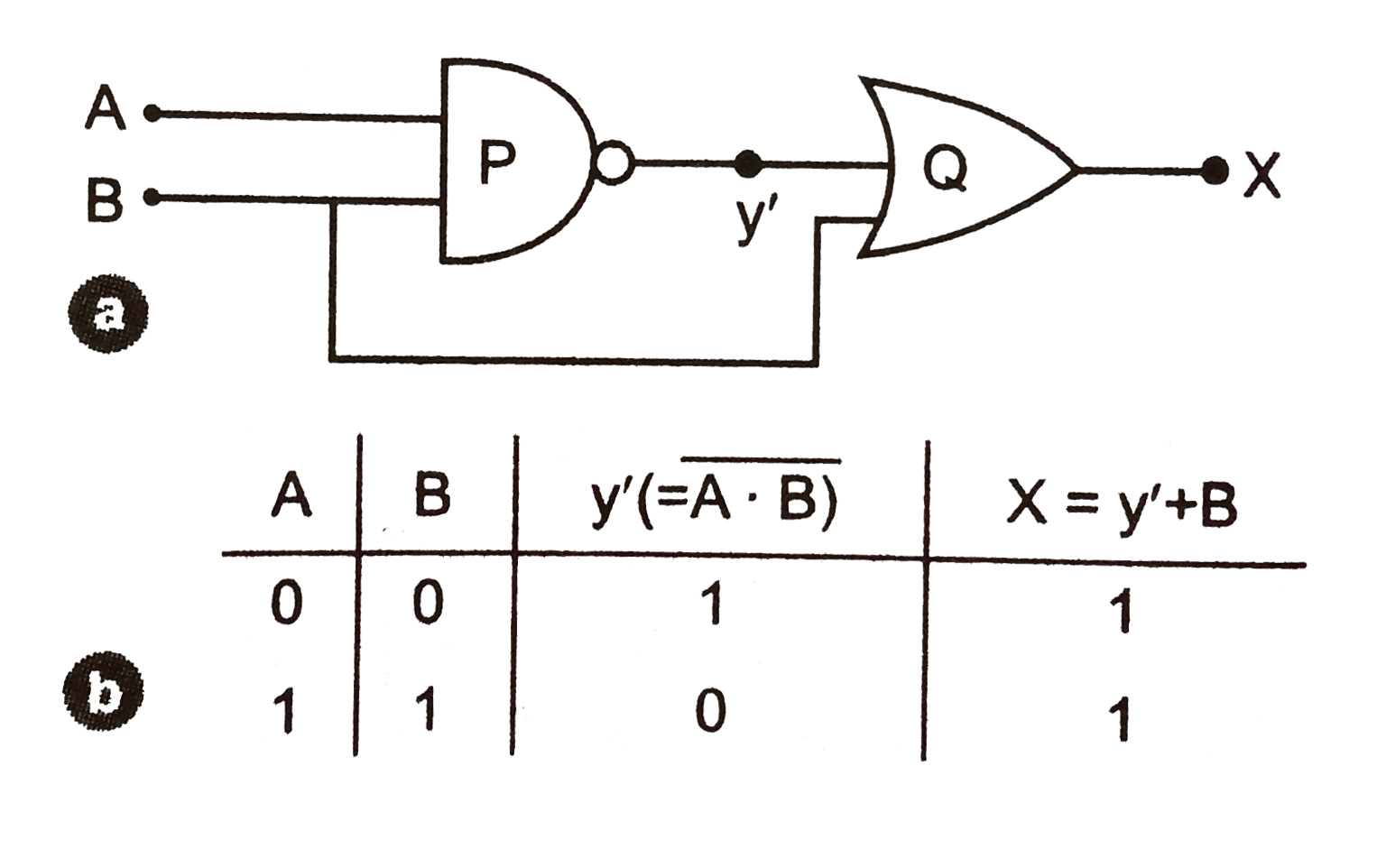
View Solution(i) Identify the logic gates marked P and Q in the given logic circuit.
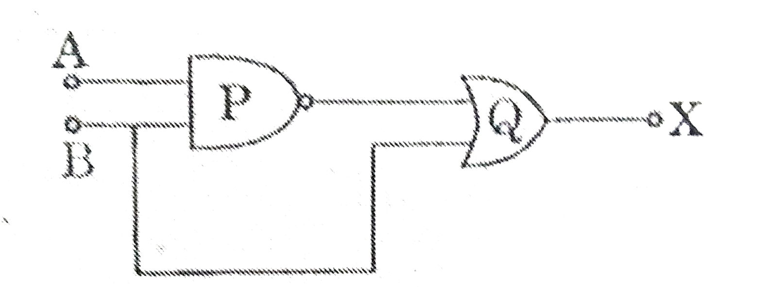
(ii) Write down the output at X for the inputs A = 0 , B = 0 and A = 1 , B = 1.
View Solution(i) Identify the logic gates marked P and Q in the given logic circuit Fig.

(ii) Write down the output at X for the inputs A=0,B=0 and A=1,B=1.
View SolutionIdentify the logic gate markeed P and Q in the given logic circuit Fig . Write down the output at X for the inputs
(i) A=0,B=0 and (ii) A=1,B=1.
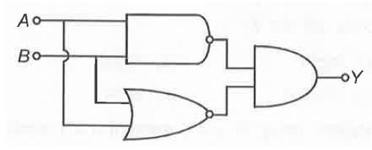
View SolutionFor the given logic gate network, the output at Y when A = 1 , B = 1 and A = 0 , B = 0 are
View SolutionIdentify the logic gates marked P and Q in the circuit Fig. Write the truth table for this combination.

View Solution


