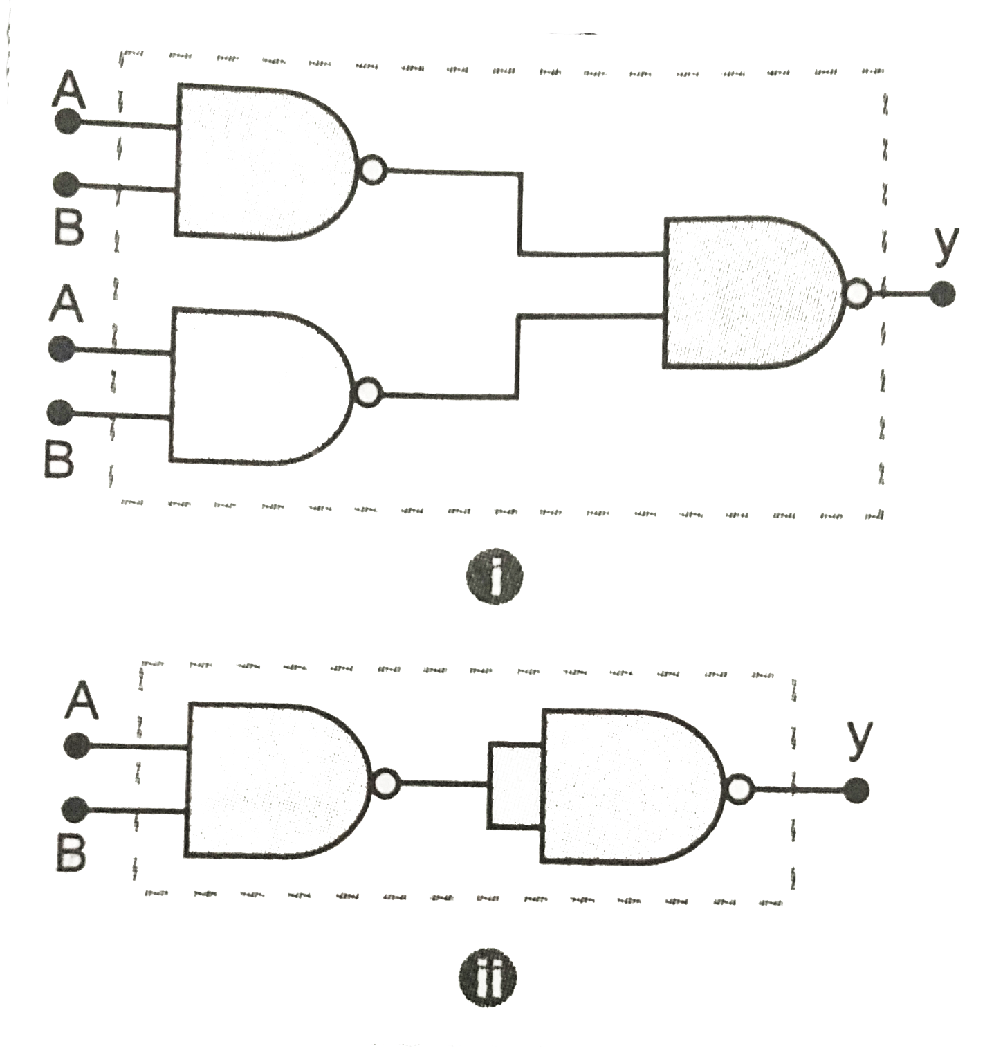
The combination of the 'NAND' gates shown here (Fig.) and (ii)) are equivalent to

A
(i) an AND gate and (ii) an AND gate
B
(i) an AND gate and (ii) an NOT gate
C
(i) an AND gate and (ii) an OR gate
D
(i) an OR gate and (ii) an NOT gate
Video Solution
Text Solution
The correct Answer is:A
The Fig. (i), represents OR gate and Fig. (ii) represents AND gate.
|
Topper's Solved these Questions
- ELECTRONIC DEVICESBook:PRADEEPChapter:ELECTRONIC DEVICESExercise:LONG QUESTION ANSWER
Explore 2 Videos
- ELECTRONIC DEVICESBook:PRADEEPChapter:ELECTRONIC DEVICESExercise:PROBLEMS FOR PRACTICE
Explore 7 Videos
- ELECTRONIC DEVICESBook:PRADEEPChapter:ELECTRONIC DEVICESExercise:HIGHER ORDER THINKING SKILLS
Explore 1 Video
- ELECTROMAGNETIC WAVESBook:PRADEEPChapter:ELECTROMAGNETIC WAVESExercise:II Focus multiple choice question
Explore 5 Videos
- ELECTROSTATICSBook:PRADEEPChapter:ELECTROSTATICSExercise:ASSERTION-REASON TYPE QUESTIONS
Explore 2 Videos
Similar Questions
Knowledge Check
NAND gate is-
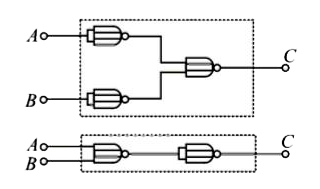
Aa basic gateBnot a universal gateCa universal gateDa universal gateThe combination of 'NAND' gates shown here in the figure below). are equivalent to :
 AAn OR gate and an AND gate respectivelyBAn AND gate and a NOT gate respectivelyCAn AND gate and an OR gate respectivelyDAn OR gate and a NOT gate respectively
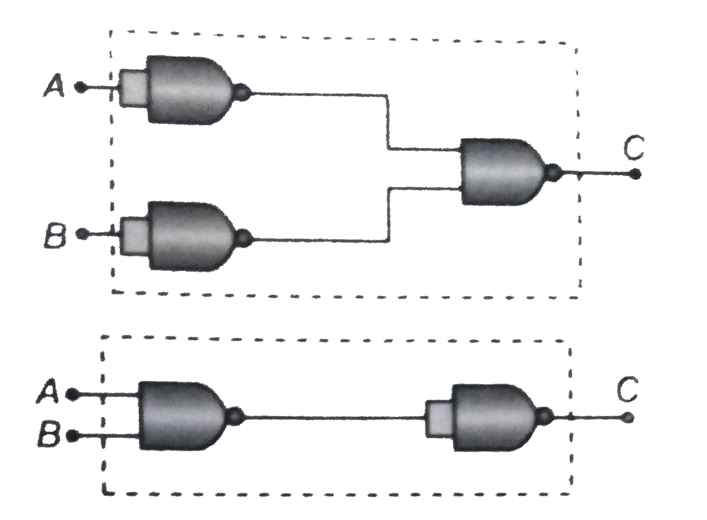
The combination of 'NAND' gates shown here under (figure) are equivalent to
 AAn OR gate and an AND gate respectivelyBAn AND gate and a NOT gate respectivelyCAn AND gate and an OR gate respectivelyDAn OR gate and a NOT gate respectively
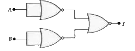
The combination of the gates shown will produce

View SolutionThe combination of the gates shown represents :-
_E01_431_Q01.png)
View SolutionThe combination of the gates shown will produce
_E01_427_Q01.png)
View SolutionThe combination of the gates shown will produce
_E01_428_Q01.png)
View SolutionThe combination of the gates shown below yields

View Solution


