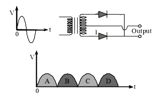
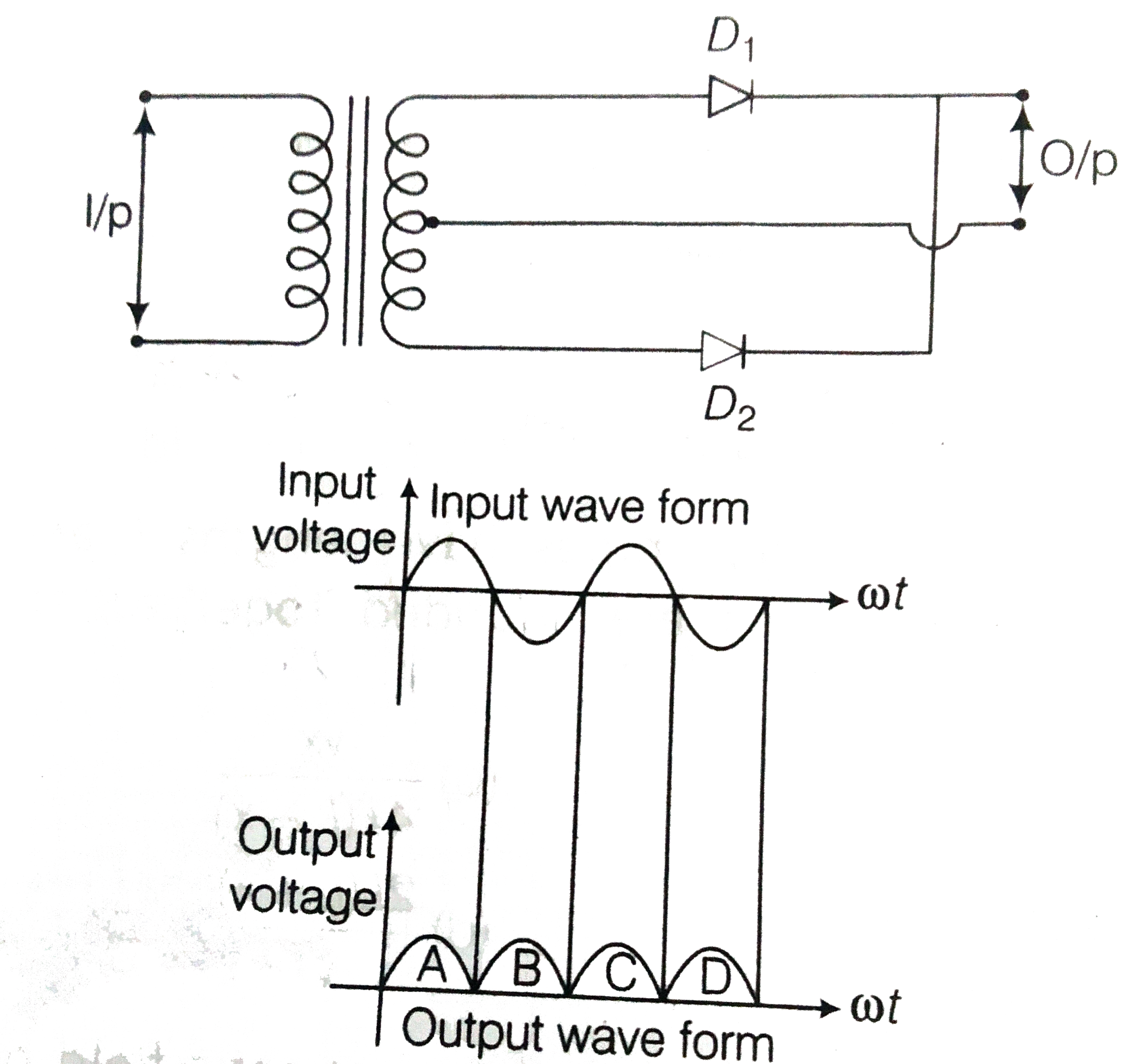
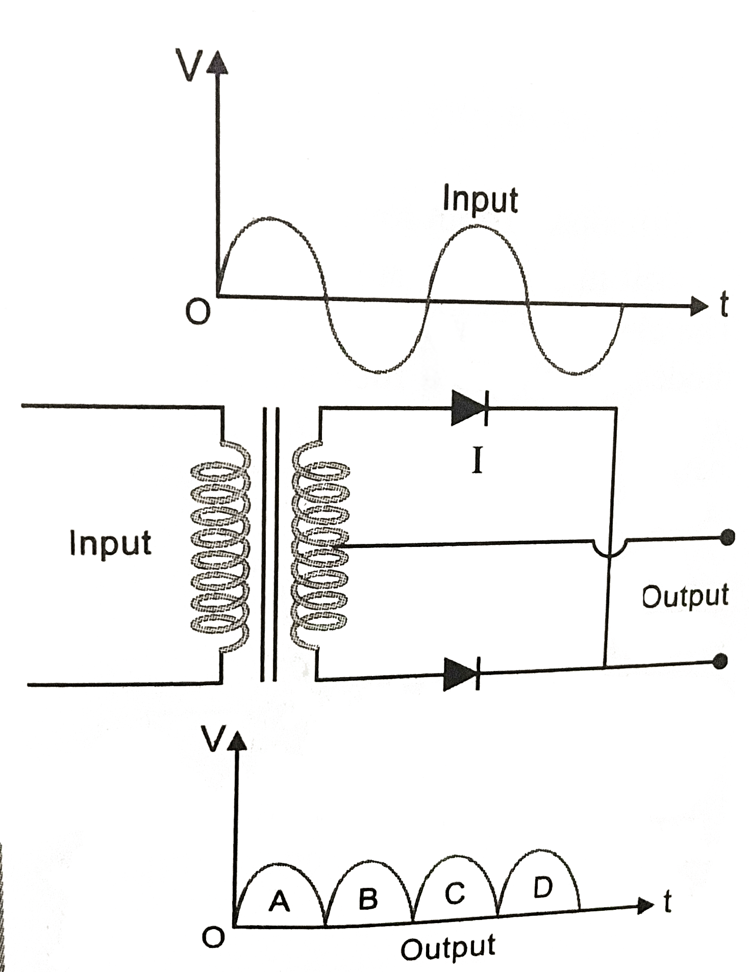
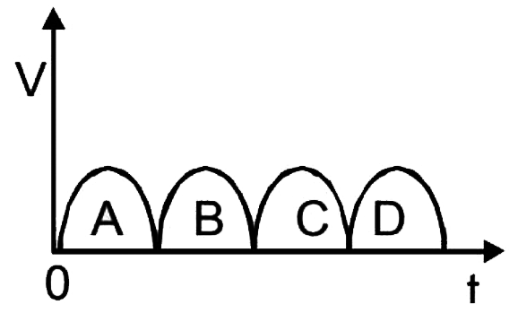
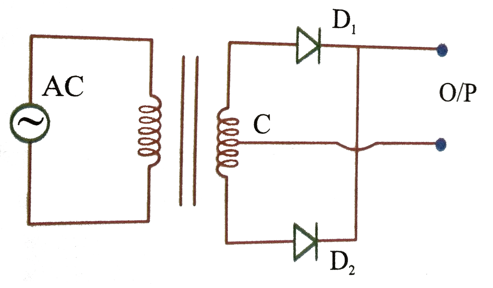
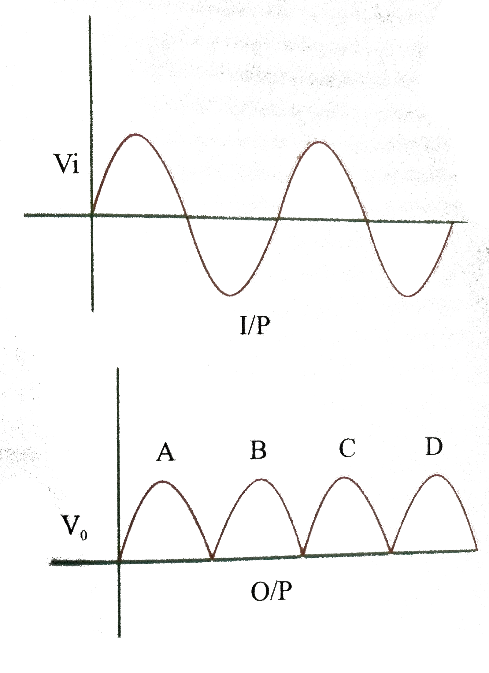
A full wave rectifier circuit along with the input and output are shown in Fig. the concentrations from the diode I is (are)
C
A, C
B, D
A, B, C, D
The correct Answer is:C
The junction diode I will provide output when forward biased. It will be so during negative half cycle of input a.c. voltage applied.
Topper's Solved these Questions
- ELECTRONIC DEVICESBook:PRADEEPChapter:ELECTRONIC DEVICESExercise:LONG QUESTION ANSWER
Explore 2 Videos
- ELECTRONIC DEVICESBook:PRADEEPChapter:ELECTRONIC DEVICESExercise:PROBLEMS FOR PRACTICE
Explore 7 Videos
- ELECTRONIC DEVICESBook:PRADEEPChapter:ELECTRONIC DEVICESExercise:HIGHER ORDER THINKING SKILLS
Explore 1 Video
- ELECTROMAGNETIC WAVESBook:PRADEEPChapter:ELECTROMAGNETIC WAVESExercise:II Focus multiple choice question
Explore 5 Videos
- ELECTROSTATICSBook:PRADEEPChapter:ELECTROSTATICSExercise:ASSERTION-REASON TYPE QUESTIONS
Explore 2 Videos
Similar Questions
Knowledge Check
A full - wave rectifier circult along the out - put is shown in figure . The contribution (s) from the diode 1 is are
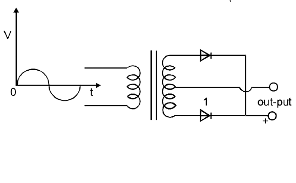 .
.
 ACBA,CCB,DDA,B,C,D
A full wave rectifier circuit along with the input and output voltages is shown in the figure
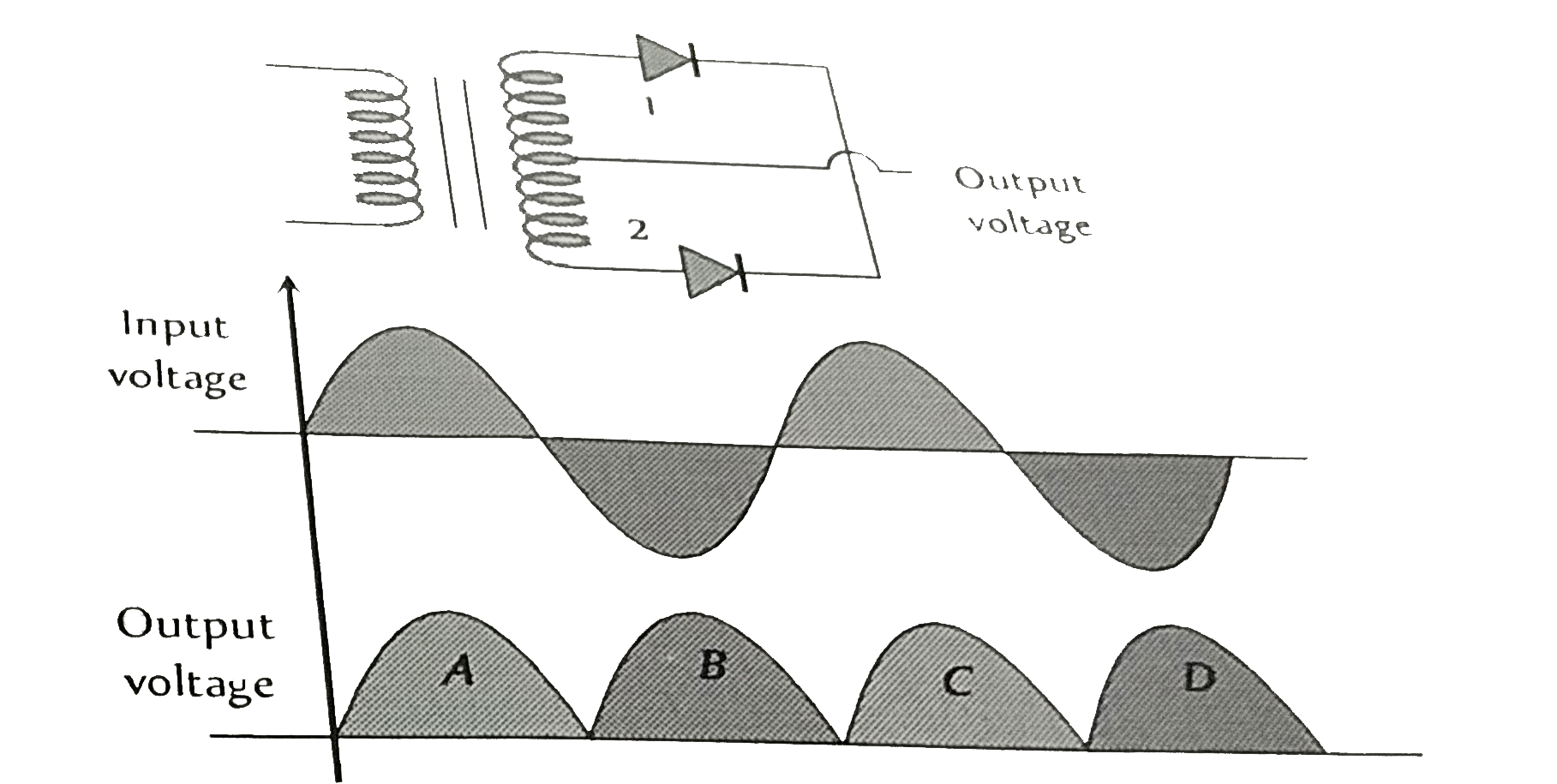
The contribution to output voltage from diode – 2 isAA,CBB,DCB,CDA,DA full wave rectifier with the output is shown in fig. the contributions from the diode (2) are.
 .
.
 ACBA,CCB,DDA,B.C,D
With the help of a labelled circuit diagram, explain how a junction diode is used as a full- wave rectifier. Draw its input and output wave formns. How do you obtain steady d.c. output from the pulsating voltage ?
View SolutionDraw a circuit diagram of a full-wave rectifier. Explain its working principle. Draw the input/output wave forms indicating clearly the function of the two diode used.
View SolutionDrawa labelled diagram of a full-wave rectifier circuit and briefly explain its working, Show the input-output waveforms.
Or
A student wants to use two p-n junction diodes to convert a.c. into d.c. Draw the labelled circuit diagram she would use and explain how it works.
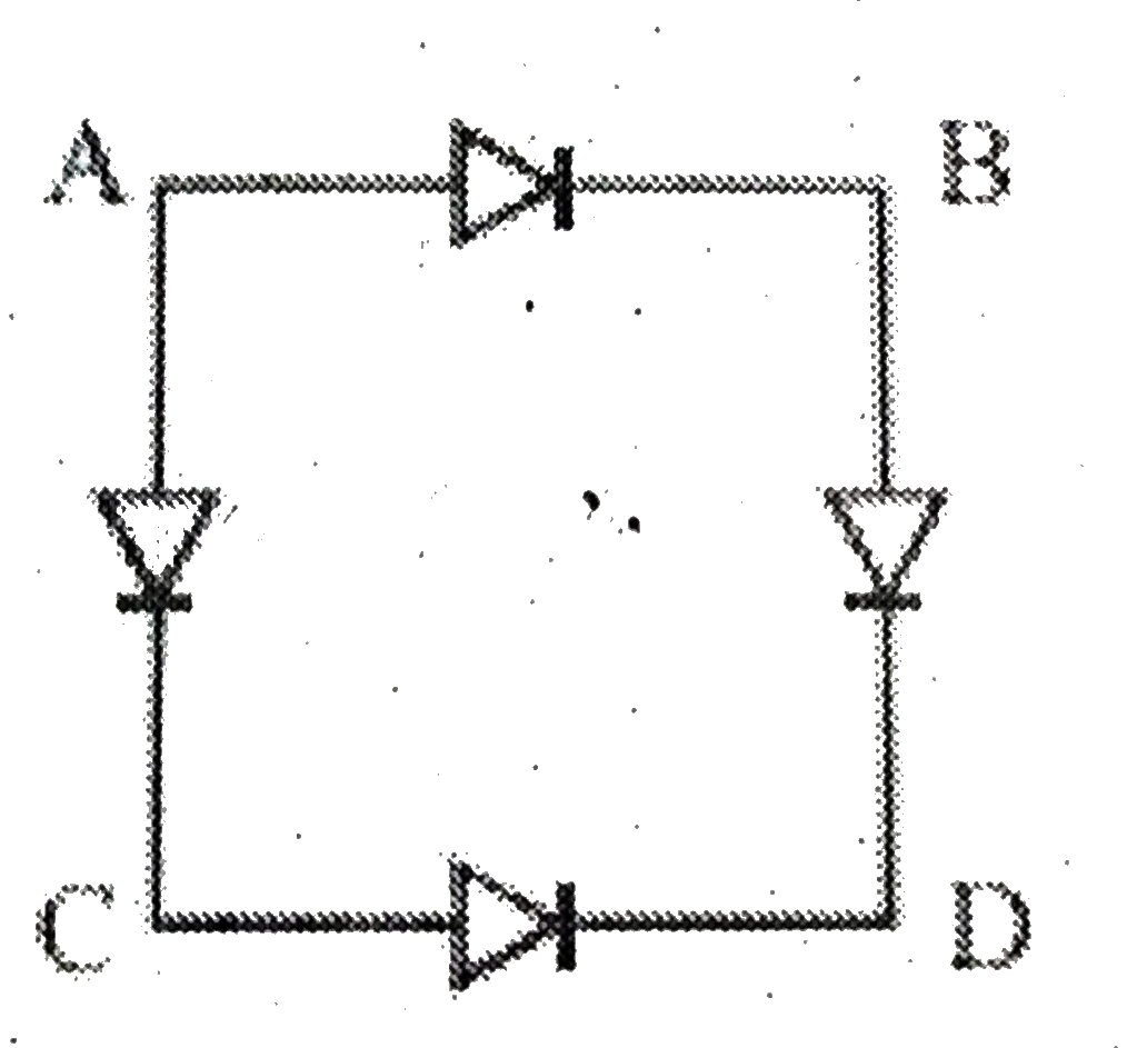
View SolutionGiven cicuit work as a full wave rectifier then input and output terminals will be respectively
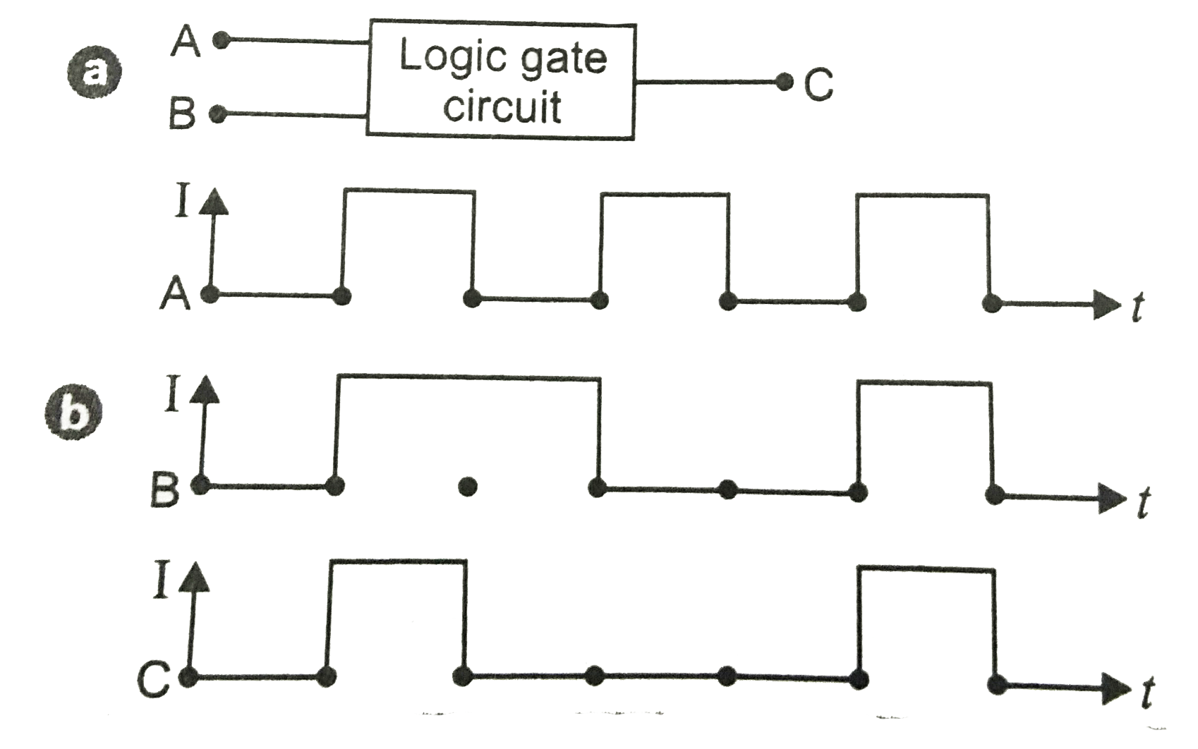
View SolutionThe Fig.shows a logic gate circuit with two inputs A and B and the output C are as shown in Fig.
View Solution


