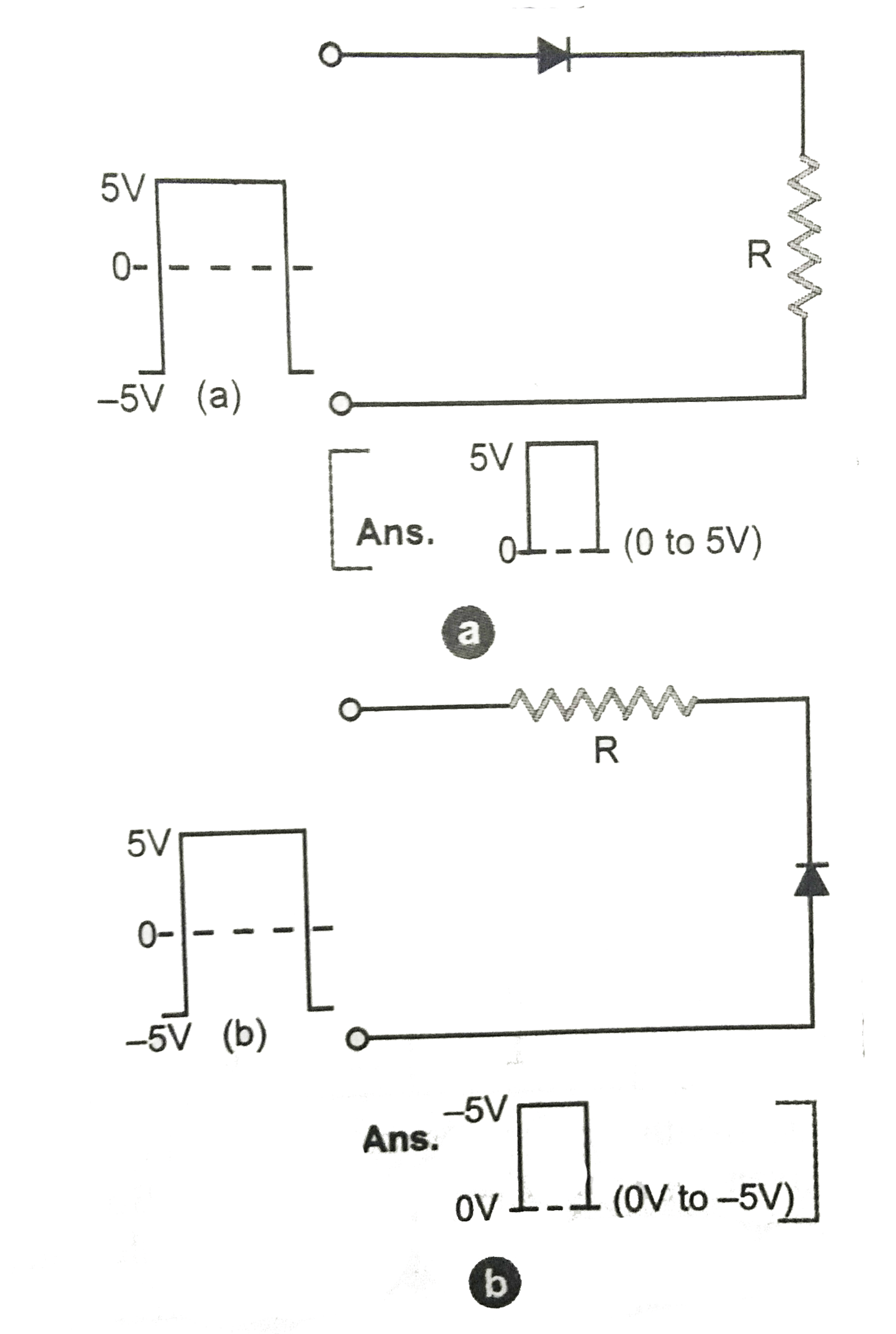
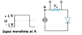
In the following circuit, if the input wave form is as shown in the figure, what will be the wave form (i) across R in Fig. and (ii) across the diode in Fig. Assume that the diode is ideal.
Video Solution
Text Solution
(i) During the positive half of wave form, p-n junction is forward biased. Due to it we get output voltage across R. During negative half of waveform, p-n junction is reversed biased. No output across R.
(ii) During the positive half of waveform, p-n junction is reverse biased and during negative half of wavefrom, p-n junction is forward biased.
|
Topper's Solved these Questions
- ELECTRONIC DEVICESBOOK - PRADEEPCHAPTER - ELECTRONIC DEVICESEXERCISE - MCQ
5 Videos
- ELECTRONIC DEVICESBOOK - PRADEEPCHAPTER - ELECTRONIC DEVICESEXERCISE - INTEGER TYPE QUESTION
2 Videos
- ELECTRONIC DEVICESBOOK - PRADEEPCHAPTER - ELECTRONIC DEVICESEXERCISE - LONG QUESTION ANSWER
2 Videos
- ELECTROMAGNETIC WAVESBOOK - PRADEEPCHAPTER - ELECTROMAGNETIC WAVESEXERCISE - II Focus multiple choice question
5 Videos
- ELECTROSTATICSBOOK - PRADEEPCHAPTER - ELECTROSTATICSEXERCISE - ASSERTION-REASON TYPE QUESTIONS
2 Videos
Similar Questions
Knowledge Check
In Fig.assuming the diode to be ideal
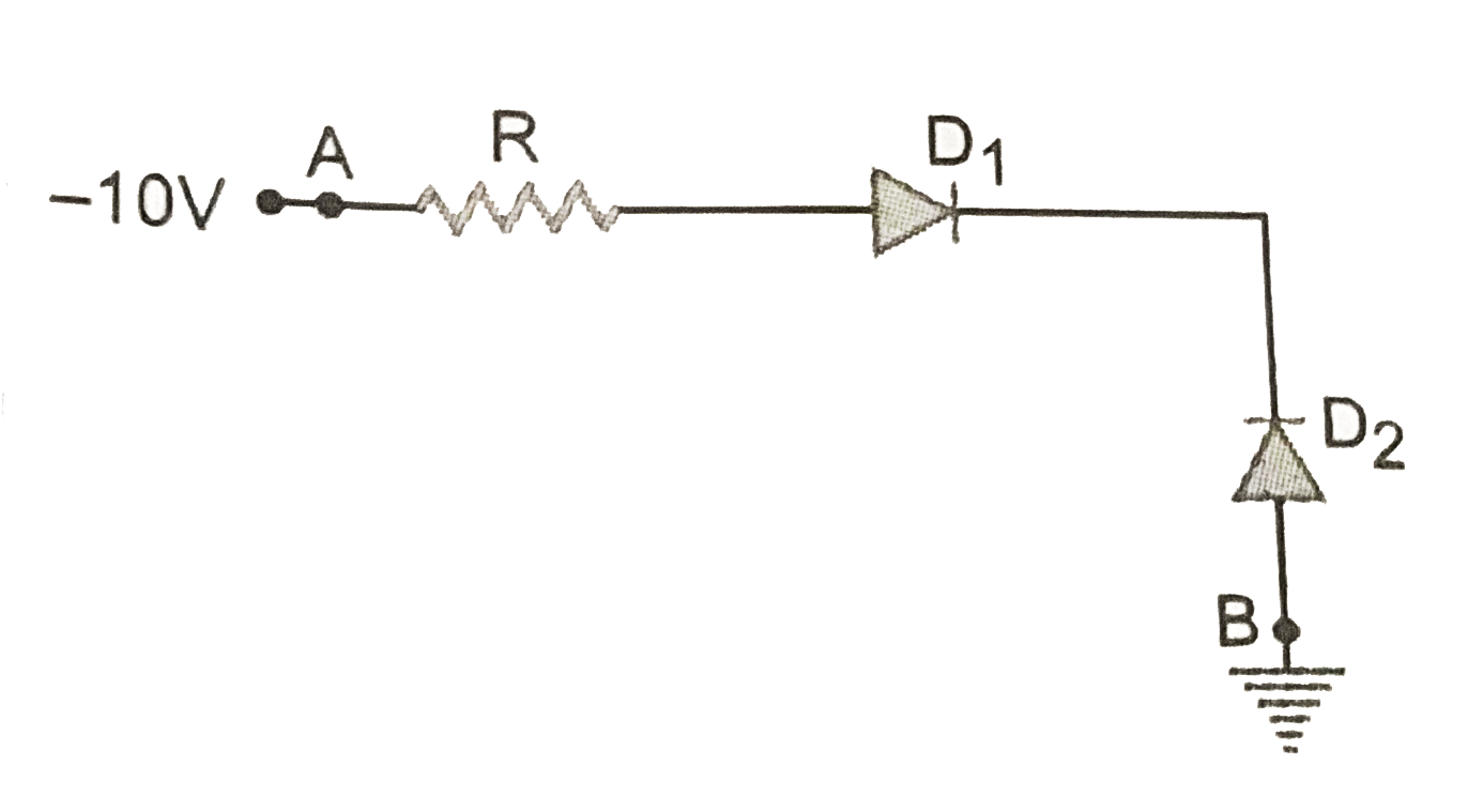 AD1 is forward biased and D2 is reverse biased and hence current flows from A to BBD2 is forward biased and D1 is reverse biased and hence no current flows from B to A and vice versaCD1 and D2 are both forward biased and hence current flows from A to BDD1 and D2 are both reverse biased and hence no current flows from A to B and vice versa
In Fig assuming the diodes to be ideal :
 AD1 is forward biased and D2 is reverse biased and hence current flow form A to BBD2 is forward biased and D1 is reverse biased and hence no current flows from B to A and vice versaCD1andD2 are both forward biased and hence current flows from A to BDD1andD2 are both reverse biased and hence no current flows from A to B and vice-versa
In the following circuit i1 and i2 are respectively
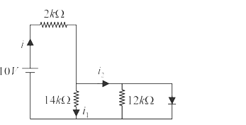 A0,0B0,5mAC5mA,0D5mA, 5mA
Draw the output wave form across the resistor
View SolutionDraw and explain the output waveform across the load resistor R, if the input wave from is as shown in Fig.

View SolutionChoose the correct waveform that can represent the voltage across R of the following circuit, assuming the diode is ideal one :
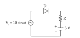
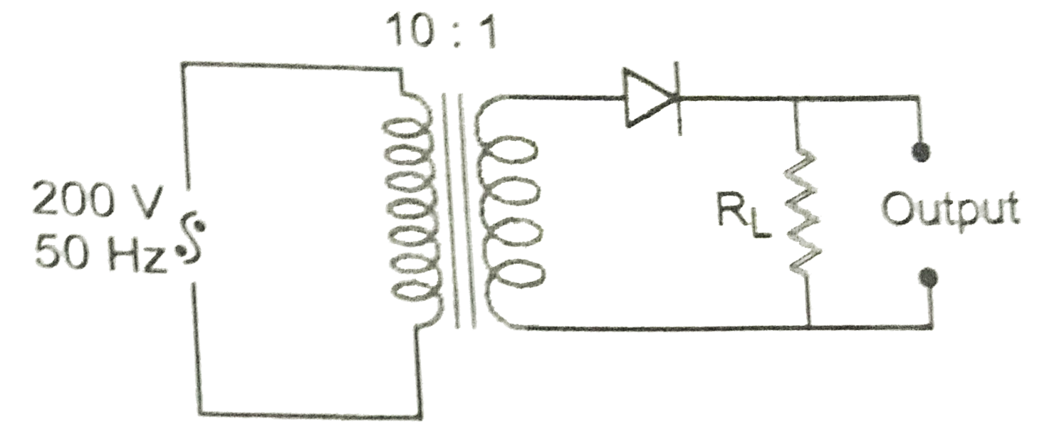
View SolutionFind the average value of d.c. voltage that can be obtained from the half wave rectifier of Fig. assuming that the diode is ideal one.
View SolutionIn a given circuit as shown the two input wave forms A and B are applied simultaneously.
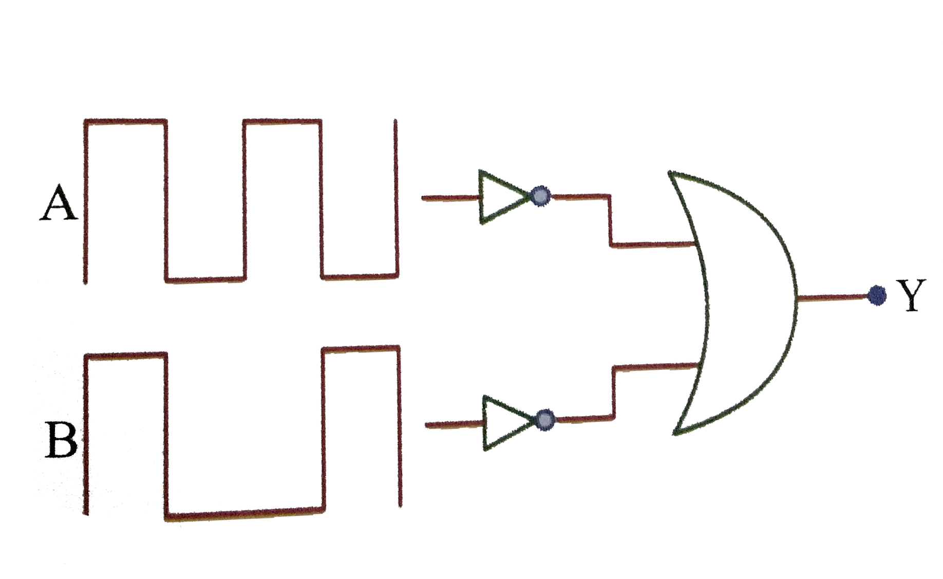
The resultant wave format at Y is.
View Solution

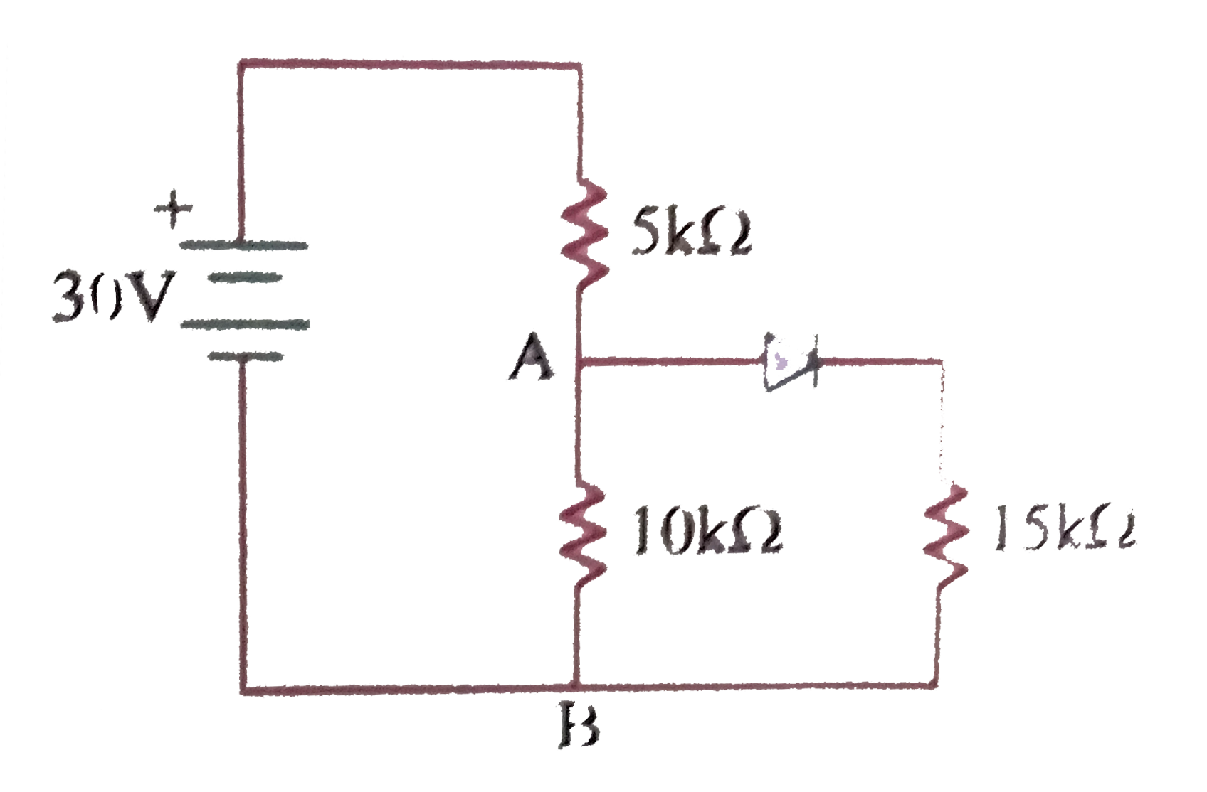 .
.